I recently published the results of measurements of the inductance of a few different decoupling layouts. This post gives the theory behind why it is desirable to keep the inductance very low.
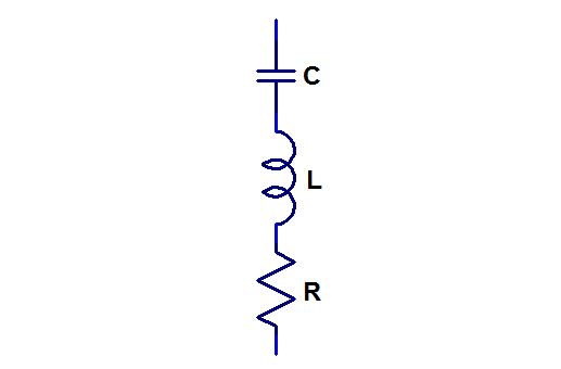
In order to keep a supply voltage on a PCB with fast circuits stable at high frequencies (kHz to hundreds of MHz), ground and power planes are used together with decoupling (or bypassing if you will) capacitors connected between the planes. At the higher end of this spectrum, the parasitic inductance of the capacitors and the tracks and vias connecting them to the planes become dominant in determining the impedance that the decoupling provides. Each capacitor together with its tracks and vias can be accurately modeled with a simple RLC series circuit:
If the impedance of such a series RLC circuit is plotted versus frequency in a log-log plot, it looks like a V:
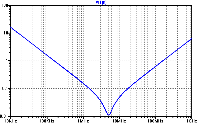
The left straight part of the V is where the capacitive reactance dominates. Here the impedance is halved for every doubling of the frequency.
The right straight part of the V is where the inductive reactance has taken over. Here the impedance doubles for every doubling of the frequency.
The lowest part of the V is where the capacitive and inductive impedances are equal and of opposite sign so that they cancel and the only thing maintaining a non-zero impedance is the series resistance. This is where the capacitor is series resonant and therefore as efficient as possible in performing its decoupling function. If the resistance is lower than the intersection of the extended straight lines from the inductive and capacitive parts of the curve, the lowest part of the curve will dip down deep, like in the plot above. This is typical of ceramic capacitors. If the resistance is higher than the intersection, the lowest part of the curve will be a horizontal flat region above the hypothetical crossing of the straight lines. This is typical for electrolytic capacitors.
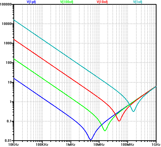
Below is a plot of the simulated impedance vs frequency for four different capacitors. All have the same series inductance (1 nH, which is typical for a reasonably well laid out 0402 capacitor). Note that except for the area around resonance, the lower value capacitors are never better than the higher value ones, so even if a 1 µF capacitor has a resonance frequency of 5 MHz, it is better (has a lower impedance) than the 1 nF capacitor (which is resonant at 160 MHz) for all frequencies up to 100 MHz and the 1 nF capacitor is only a little better in a relatively small region around its resonance frequency).
Since the inductance dominates the total capacitor impedance for such a large range of interesting decoupling frequencies, it is important to keep it as low as possible. It is also important for another reason, namely that troublesome parallel resonances are formed when paralleling capacitors of different characteristics and that the amplitude of the parallel resonances is highly dependent upon the inductance.
The planes have a relatively small capacitance, and therefore there will always be at least one parallel resonant peak when decoupling capacitors are attached to a plane. The equivalent circuit (valid up until frequencies where the plane starts to show its own resonances due to its distributed nature) of a decoupling capacitor and a plane is shown below.
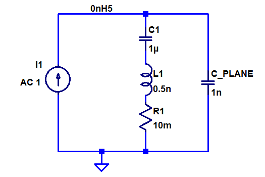
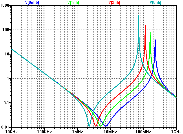
Below is a plot of the total impedance of a 1 nF plane capacitance in parallel with a 1 µF decoupling capacitor with 0.5 nH (blue), 1 nH (green), 2 nH (red) and 5 nH (blue-gray) parasitic inductance. As can be seen, the inductive parts of the curves are higher for the higher inductances and also the parallel resonant peaks are higher in amplitude and lower in frequency when the decoupling capacitor has a higher inductance.
So it is apparently a good idea to keep the inductance of the decoupling capacitors low. Since surface mount capacitors are essentially just small rectangular blocks without leads, their inherent inductance (although strictly not so well defined) is rather low and the PCB layout (PCB tracks and vias) can and does add significantly to the total inductance of the capacitor. It is therefore of interest to know what impact different layouts have on the inductance and in order to put somewhat hard numbers on different layouts, I designed and measured the test board described in the previous post.
One thought on “Decoupling Primer”