In my previous blog post about the inductance of some decoupling layouts, I concluded that using two 0402 capacitors would (almost) always be a better choice than using one 0306 capacitor. Andrew commented that mutual inductance might have an effect and he wanted to see measurements of layouts where two 0402 capacitors were present. Fortunately, my test layout supports that and I have now made a few extra measurements to see how two 0402s in parallel actually performs.
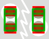
Here is a picture of the top side of the layout with the relevant components in color. For more details about the layout see the previous blog post.

The new combinations I tested were capacitors on:
- C110 and C117; two 0402s close to each other (but connected in reverse) taking up roughly the same area as one 0306.
- C110 and C112; two 0402s far from each other and thus without inductive coupling.
- The same cases as above but on the bottom side of the PCB and thus further from the planes.
- I also include old data for the 0306 at position C132 for comparison as well as data for the single 0402 at C112.
Case 1 might give some inductive coupling between the components and vias, especially on the bottom side where the vias are longer and the capacitors are further from the planes. The coupling should help reduce the inductance since the currents in the nearby capacitors and vias flow in opposite directions.
Here is an impedance plot comparing the impedance of one 0306 to that of two 0402s on the top side of the board.
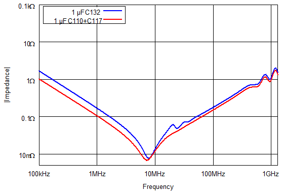
The dual 0402 is the winner since it has lower impedance for all frequencies. The reason it has lower impedance at low frequencies is that the combination has higher capacitance. Interestingly though, it does not quite have twice the capacitance of a single 1 µF 0306. (In my experience, 1 µF 0402 capacitors are always a bit below 1 µF and they are also much more voltage dependent than 1 µF capacitors in larger packages. So do not count on getting 1 µF of capacitance from an 0402 capacitor, especially not if you have some voltage across it.)
Below is the table with the results of the measurements. Layouts E and G were presented in the previous blog post whereas I and J are new.
| E | G | |
|---|---|---|
| Layout | 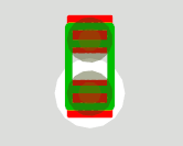 |
 |
| Desc | 0402 via in pad 0.3/0.6 mm vias C/C = 0.7 mm |
0306 via in pad 0.3/0.6 mm vias C/C = 0.7 mm |
| Top | 0.44 nH | 0.28 nH |
| Bottom | 1.04 nH | 0.62 nH |
| I | J | |
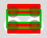
| Layout | 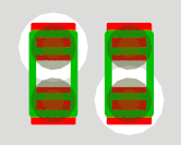 |
 |
| Desc | Dual 0402 close together via in pad 0.3/0.6 mm vias C/C = 0.7 mm |
Dual 0402 far away via in pad 0.3/0.6 mm vias C/C = 0.7 mm |
| Top | 0.24 nH | 0.21 nH |
| Bottom | 0.51 nH | 0.51 nH |
Observations
- In both cases of dual 0402 layouts, the inductance was less than the inductance of the best 0306 layout, just as predicted.
- The two 0402 that were placed close together had a slightly higher inductance on the top side than the other variant, despite the inductive coupling that should help reduce the inductance. Maybe this is measurement error or maybe the result is caused by differences in plane imperfections (anti-pads) close to the capacitors. Or perhaps it is the result of that the current going to both capacitors flows in the same part of the planes, whereas current flows in different parts of the planes when the capacitors are far away so that the plane inductances appear in parallel.
- If the latter is the main reason for the difference in top side inductance, the fact that the bottom side inductances came out the same might be explained by the additional plane inductance being offset by the reduction in inductance caused by the inductive coupling between the (long) vias and the components that are far from the planes. The inductive coupling is likely to have a bigger effect on the bottom side since the vias are longer and the capacitors are further from the planes.
So, the prediction from the previous blog post that using 0402s is a better idea than using half as many 0306s holds up well.
2 thoughts on “More Decoupling Layout Inductance Measurements”