There is a newer version of this antenna in the following post: “Improved 2 m Fox Hunting Antenna“.
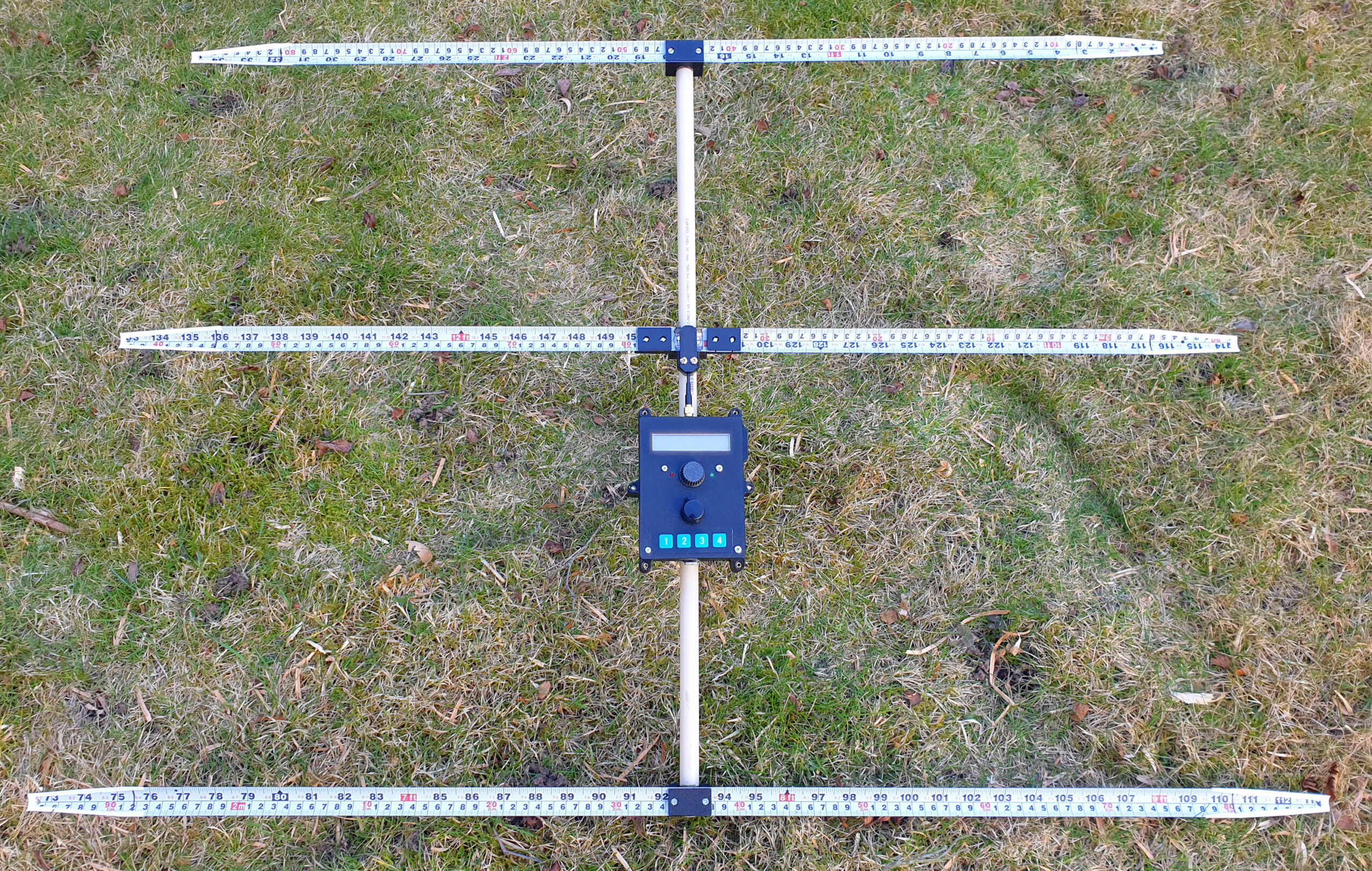
This article describes a Yagi antenna I have designed for use in a “fox hunting” receiver for the 2 m band (144 MHz). The antenna uses 25 mm wide steel tape measure for the elements, 16 mm PVC pipe as the boom and 3D-printed parts to keep it all together. Models for the 3D-printed parts are available for download.
Link to a zip-file with 3MF models of the parts:
Several Yagi antenna designs for the sport of fox hunting (or ARDF, amateur radio direction finding) have been published and can be found by some searching on the web. I decided to have a go at designing such an antenna myself and used the free YagiCAD program to do so. After a number of rounds of optimization starting from different base designs, I ended up with the following:
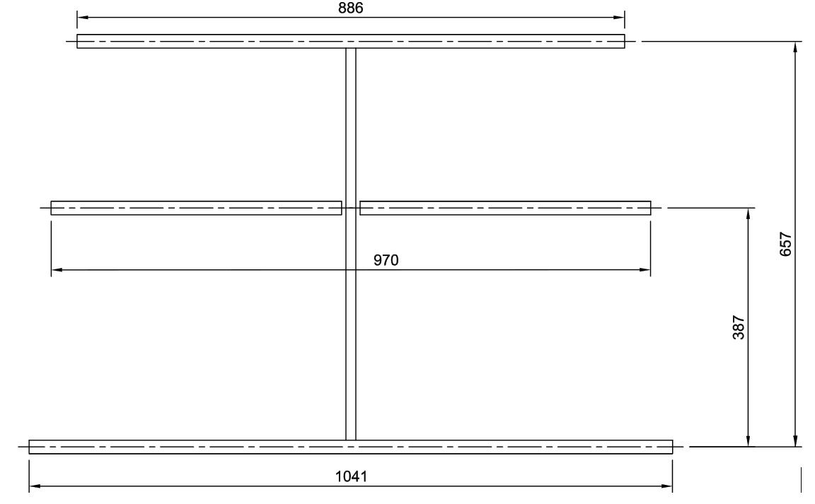
The shortest element is the director (towards antenna main lobe) while the longest is the reflector. The “driven” element is the one in the middle.
According to YagiCAD, the radiation pattern of the antenna is as follows:
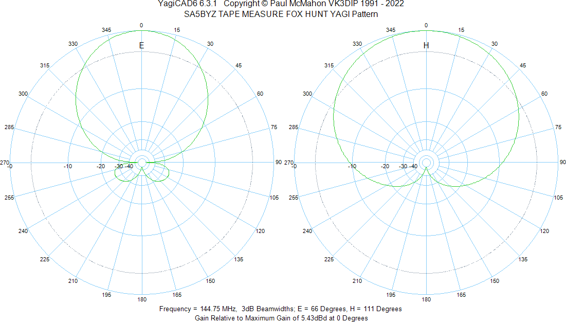
Front-to-back ratio is simulated to be above 40 dB.
While I have not measured the real antenna diagram, the subjective assessment is that the antenna performs well. Using a network analyzer, I have found that it’s impedance is around 40 -j0 ohms at 145 MHz.
For the beam, I used a piece of 16 mm outside diameter PVC electrical conduit pipe (“VP-rör” in Swedish).
For the elements, I used 25 mm wide steel tape measure from Biltema, e.g. part number 16-2931.
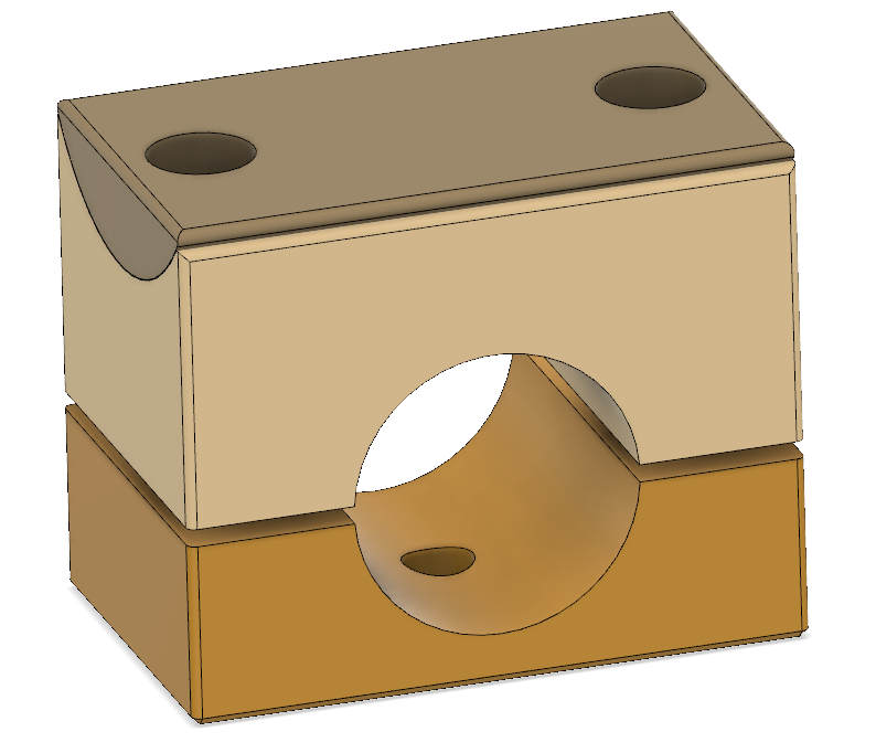
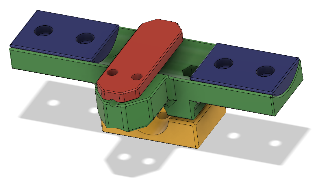
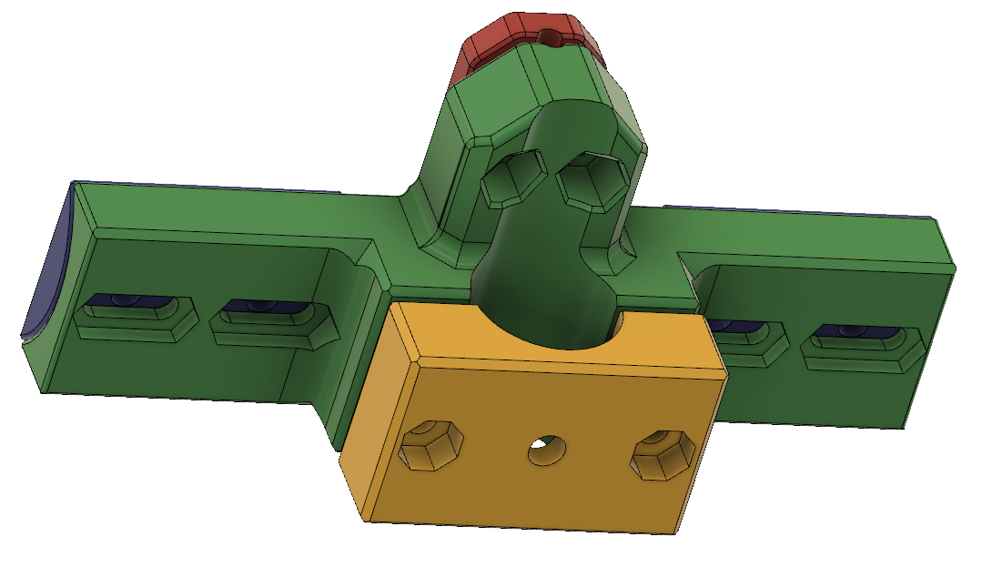
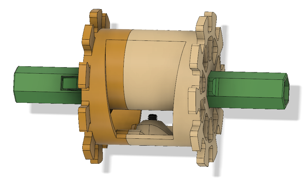
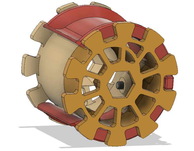
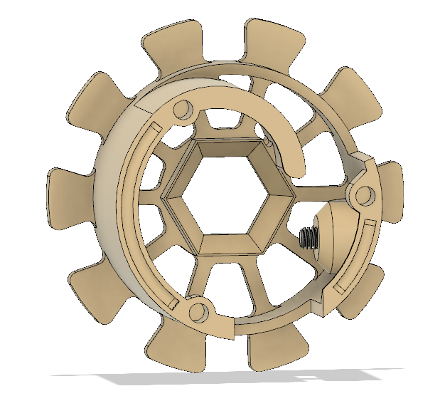
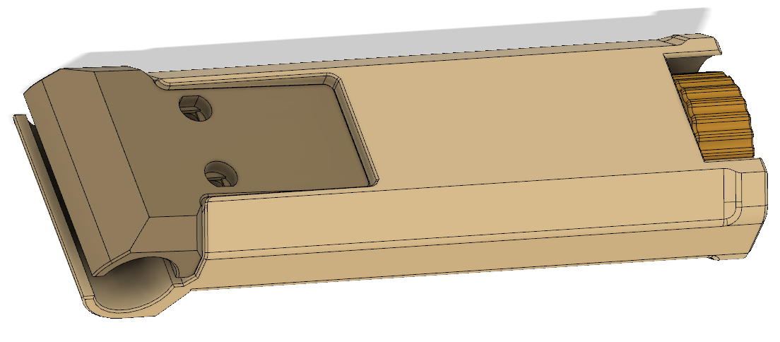
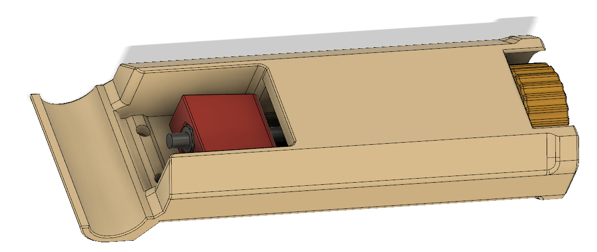
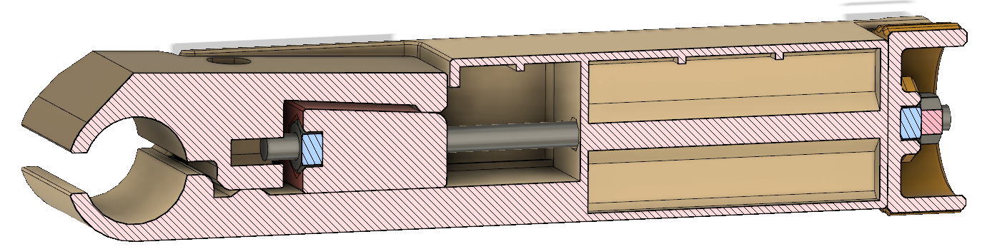
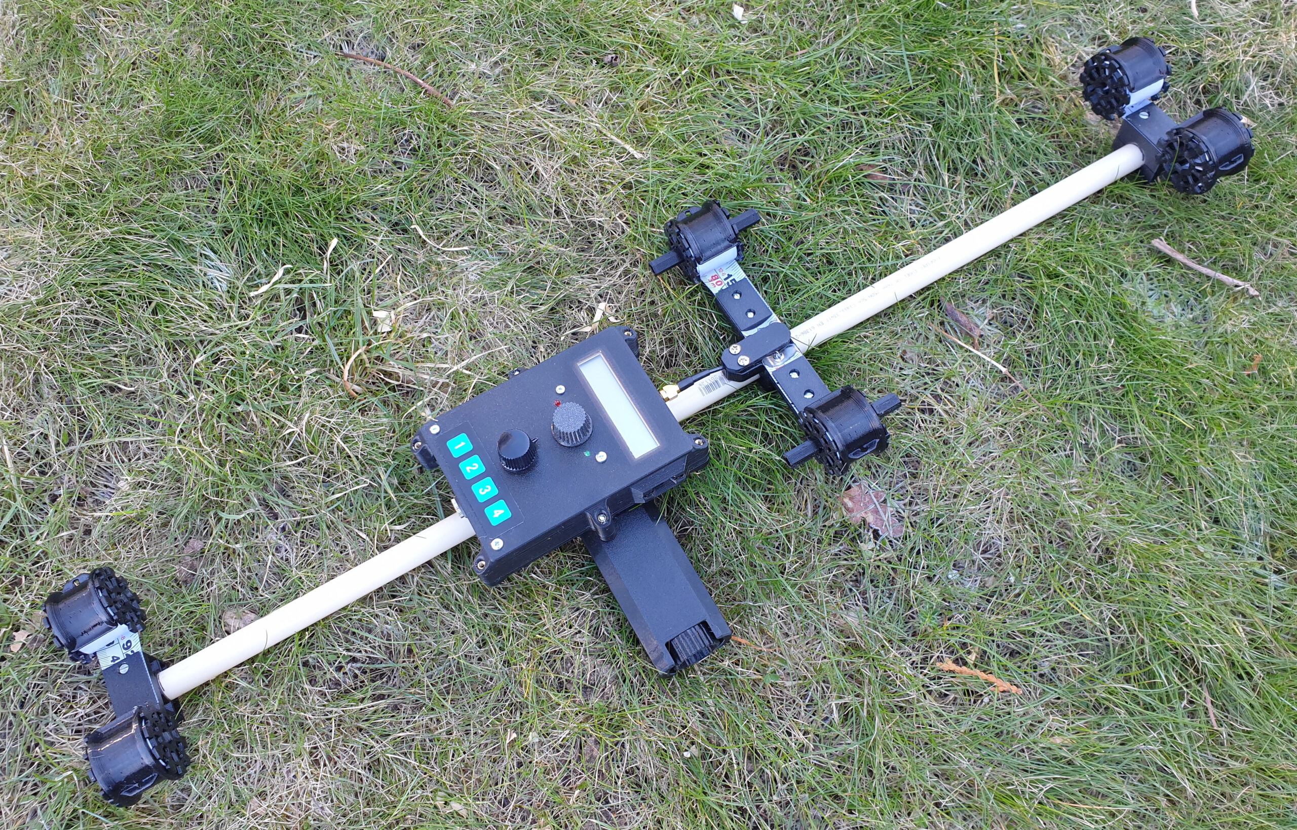
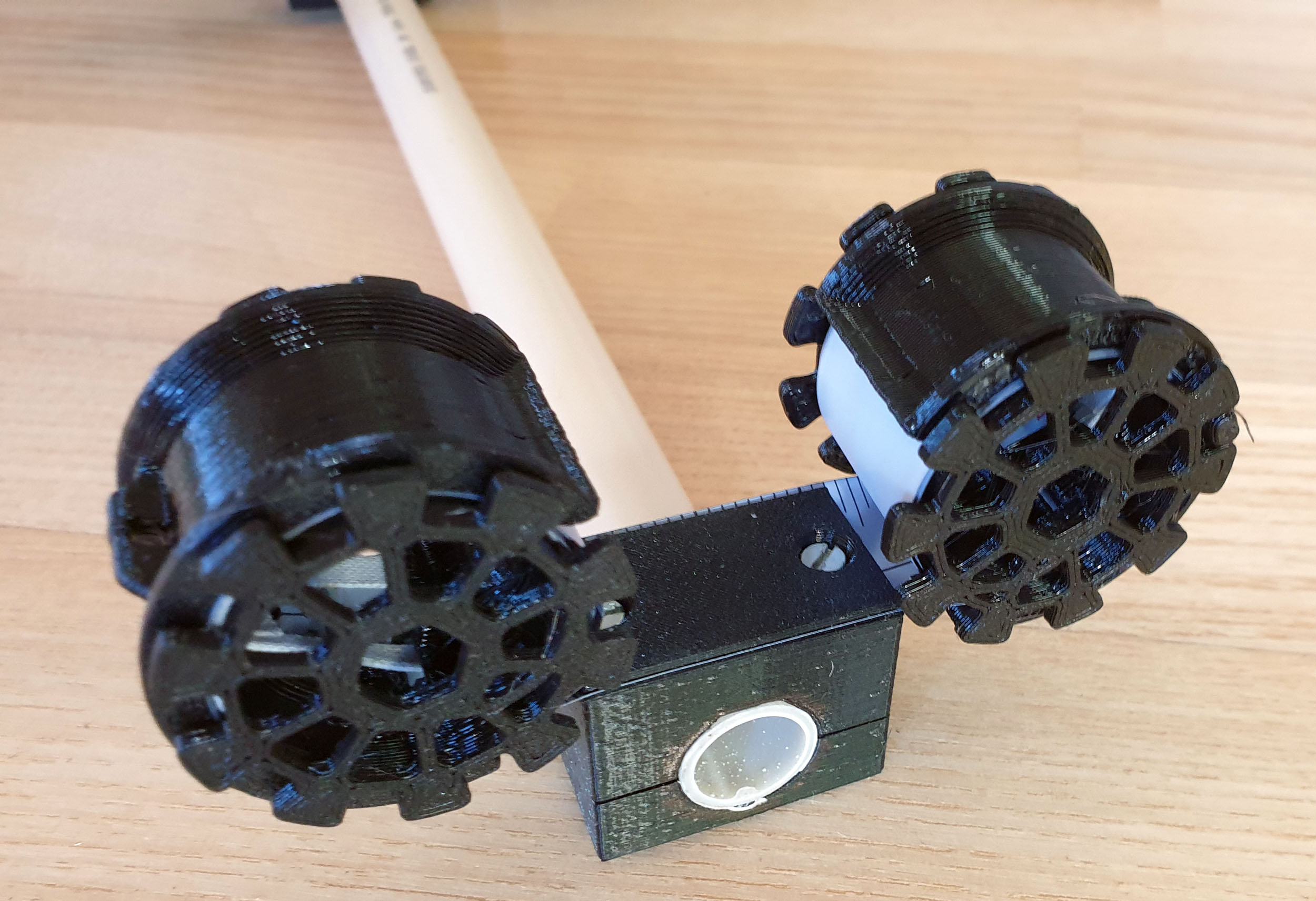
To mechanically connect the elements to the beam, I designed various clamps that I printed on my 3D printer. The antenna needs to be made smaller for storage and transportation, so I also designed spools and clamps to allow the elements to be rolled up and kept securely in that state. Furthermore, I have designed a handle that can grip on the pipe and be secured by a screw pulling a wedge. Pictures of all these parts are shown below.