In this post I describe some code I wrote to handle the input from an incremental rotary encoder connected to a Teensy. The code should work well also on an Arduino, provided the rotary encoder signals are connected to pins that have interrupt functionality.
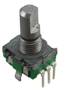
A rotary encoder is great for many kinds of user interfaces. It physically looks like a potentiometer, but it is not limited to less than one turn. The output is digital, so it can relatively easily be interpreted by a micro controller, even one without a built-in analog to digital converter.
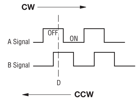
The number of pulses per rotation can vary, but between 12 and 24 is common. An encoder contains two switches and if it is rotated clockwise, switch A closes before switch B for each “click” and if it is turned counter clockwise, switch B closes before switch A. This is called quadrature encoding since the two square waves are 90 degrees out of phase from each other.
By looking at the order in which the switches close, it is possible to determine in which direction the knob is turned. The figure below illustrates the waveforms, assuming the switches connects their pins to ground and that the two signals are otherwise pulled up to a positive voltage by pull-up resistors.
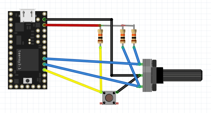
Below is a diagram showing how a rotary encoder and a push button (which is often integrated into the encoder) can be hooked up to a Teensy 3.1.
A problem when trying to use a rotary encoder as part of a user interface in an embedded application is that the pulses can be pretty short and it is important to not miss any, as that would mean missed rotations or even rotations detected in the wrong direction. Furthermore, like for almost all switches, there is also contact bounce that one must handle in some way. Typically, the processor has to do other things while also responding to input from the rotary encoder.
This means that it is often very hard or impossible to robustly interpret the signals from an encoder by polling the signals from within the main loop of the program. To get around this problem, one can instead use interrupt routines that are triggered when a signal from the encoder changes level. This is precisely what the code below does. It was written for a Teensy 3.1 (or 3.2), but should work on other platforms as long as the encoder signals are connected to pins with interrupt capability.
The following function call
attachInterrupt(digitalPinToInterrupt(rotAPin), ISRrotAChange, CHANGE);
sets up an the function “ISRrotAChange()” to be called every time the rotAPin changes state. This function in turn looks at the pin and sets the rotAval variable accordingly before calling the more complicated function UpdateRot() which contains a state machine that keeps track of what the rotary encoder is doing and increments or decrements the rotAcc (rotary encoder accumulator) variable when it has determined that the encoder has moved a notch. No debounce timer is necessary since it is pretty safe to assume that the bounces of one switch will have died out before the next switch will be activated.
The rotAcc variable is changed only after the second signal becomes activated (low) while the first signal is still active since it is pretty common that one signal is activated and later deactivated without the second signal becoming active. This happens when the operator rotates the knob a fraction of a notch and then lets it return to the original position without going all the way to the next notch.
The main loop must not look directly at the rotAcc variable since it can be changed at any point within the program by an interrupt. It is only safe to access it while interrupts are disabled, so accesses have to be surrounded by cli() (clear interrupt enable bit) and sei() (set interrupt enable bit) function calls. This is done in the GetRotAcc() function which thus provides a convenient way of safely looking at the value of the accumulator. The interrupt service routines (ISRs) themselves do not need to mess with cli() and sei() when accessing the interrupt state variables since interrupts are automatically temporarily disabled while servicing an interrupt.
Since the global variables used by the interrupt routines can be changed at any point within the course of the main program, they have to be be declared with the keyword “volatile” to prevent the compiler from making optimizations that assume that they behave like normal variables that will never magically change under the feet of the main program code.
Expand the Teensy codeTarget: Teensy 3.1
Written by Per Magnusson, http://www.axotron.se
v 1.0 2015-11-15
This program is public domain.
*/
// Rotary encoder push button pin, active low
static const int pushPin = 16;
// Rotary encoder phase A pin
static const int rotBPin = 17;
// Rotary encoder phase B pin
static const int rotAPin = 18;
#define DEMO 1
// Rotary encoder variables, used by interrupt routines
volatile int rotState = 0;
volatile int rotAval = 1;
volatile int rotBval = 1;
volatile int rotAcc = 0;
void setup()
{
Serial.begin(57600);
pinMode(rotAPin, INPUT);
pinMode(rotBPin, INPUT);
pinMode(pushPin, INPUT);
attachInterrupt(digitalPinToInterrupt(rotAPin),
ISRrotAChange, CHANGE);
attachInterrupt(digitalPinToInterrupt(rotBPin),
ISRrotBChange, CHANGE);
}
void loop()
{
static int oldRotAcc = 0; // Remember previous state
int newRotAcc;
// Do not look directly at the rotary accumulator variable,
// it must be done in an interrupt safe manner
newRotAcc = GetRotAcc();
if(!digitalRead(pushPin)) {
// The button was pushed.
// Button detection is not interrupt driven, but detection of the
// rotary encoder movements goes on also in the busy way below.
Serial.println("Button down");
delay(10); // Debounce
while(!digitalRead(pushPin))
;
delay(10); // Debounce
Serial.println("Button up");
} else if(newRotAcc != oldRotAcc) {
// The encoder was rotated at least one step.
Serial.println(newRotAcc);
oldRotAcc = newRotAcc;
}
}
// Return the current value of the rotaryEncoder
// counter in an interrupt safe way.
int GetRotAcc()
{
int rot;
cli();
rot = rotAcc;
sei();
return rot;
}
// Interrupt routines
void ISRrotAChange()
{
if(digitalRead(rotAPin)) {
rotAval = 1;
UpdateRot();
} else {
rotAval = 0;
UpdateRot();
}
}
void ISRrotBChange()
{
if(digitalRead(rotBPin)) {
rotBval = 1;
UpdateRot();
} else {
rotBval = 0;
UpdateRot();
}
}
// Update rotary encoder accumulator.
// This function is called by the interrupt routines.
void UpdateRot()
{
// Increment rotAcc if going CW, decrement it if going CCW.
// Do not increment anything if it was just a glitch.
switch(rotState) {
case 0: // Idle state, look for direction
if(!rotBval) {
rotState = 1; // CW 1
}
if(!rotAval) {
rotState = 11; // CCW 1
}
break;
case 1: // CW, wait for A low while B is low
if(!rotBval) {
if(!rotAval) {
rotAcc++;
#ifdef DEMO
// Remove this when not in demo mode
Serial.print(" right ");
#endif
rotState = 2; // CW 2
}
} else {
if(rotAval) {
// It was just a glitch on B, go back to start
rotState = 0;
}
}
break;
case 2: // CW, wait for B high
if(rotBval) {
rotState = 3; // CW 3
}
break;
case 3: // CW, wait for A high
if(rotAval) {
rotState = 0; // back to idle (detent) state
}
break;
case 11: // CCW, wait for B low while A is low
if(!rotAval) {
if(!rotBval) {
rotAcc–;
#ifdef DEMO
// Remove this when not in demo mode
Serial.print(" left ");
#endif
rotState = 12; // CCW 2
}
} else {
if(rotBval) {
// It was just a glitch on A, go back to start
rotState = 0;
}
}
break;
case 12: // CCW, wait for A high
if(rotAval) {
rotState = 13; // CCW 3
}
break;
case 13: // CCW, wait for B high
if(rotBval) {
rotState = 0; // back to idle (detent) state
}
break;
}
}
[/cpp]
In this demo version of the code, status information is sent back over the USB serial port so that a terminal window (e.g. the one in the Arduino environment) can display it. The texts “left” or “right” are printed by the ISR when it changes the value of rotAcc and the main loop prints the value of rotAcc when it detects that it has changed.
The main loop handles the push button. This is done through normal polling. A delay is used to filter out contact bounces. While the button is held down, the main loop is stuck and cannot print updated rotAcc values, but the ISR routines happily execute if the encoder is rotated, so the “left” and “right” strings can still appear while the button is pressed.
Here is an excerpt from a terminal session:
 right 1
 right 2
 right 3
 right 4
 right 5
 left 4
 left 3
Button down
 right  right  right  right  left  right Button up
7
 right 8
 right 9
 left 8
 left 7
The encoder was rotated clockwise (CW) five steps (right 1 to right 5) and then counter clockwise (CCW) by two steps (left 3). Then the button was pushed and held down (Button down) while the encoder was rotated four notches CW, one CCW and one CW before the button was released. After this the main loop resumed and detected that the rotAcc value had changed to 7. Then the encoder was rotated two more notches CW and two CCW.
When not using this to demo the functionality of these specific routines, the Serial.print() statements in the interrupt routines should be removed, either by not #defining DEMO or by removing those lines of code completely.