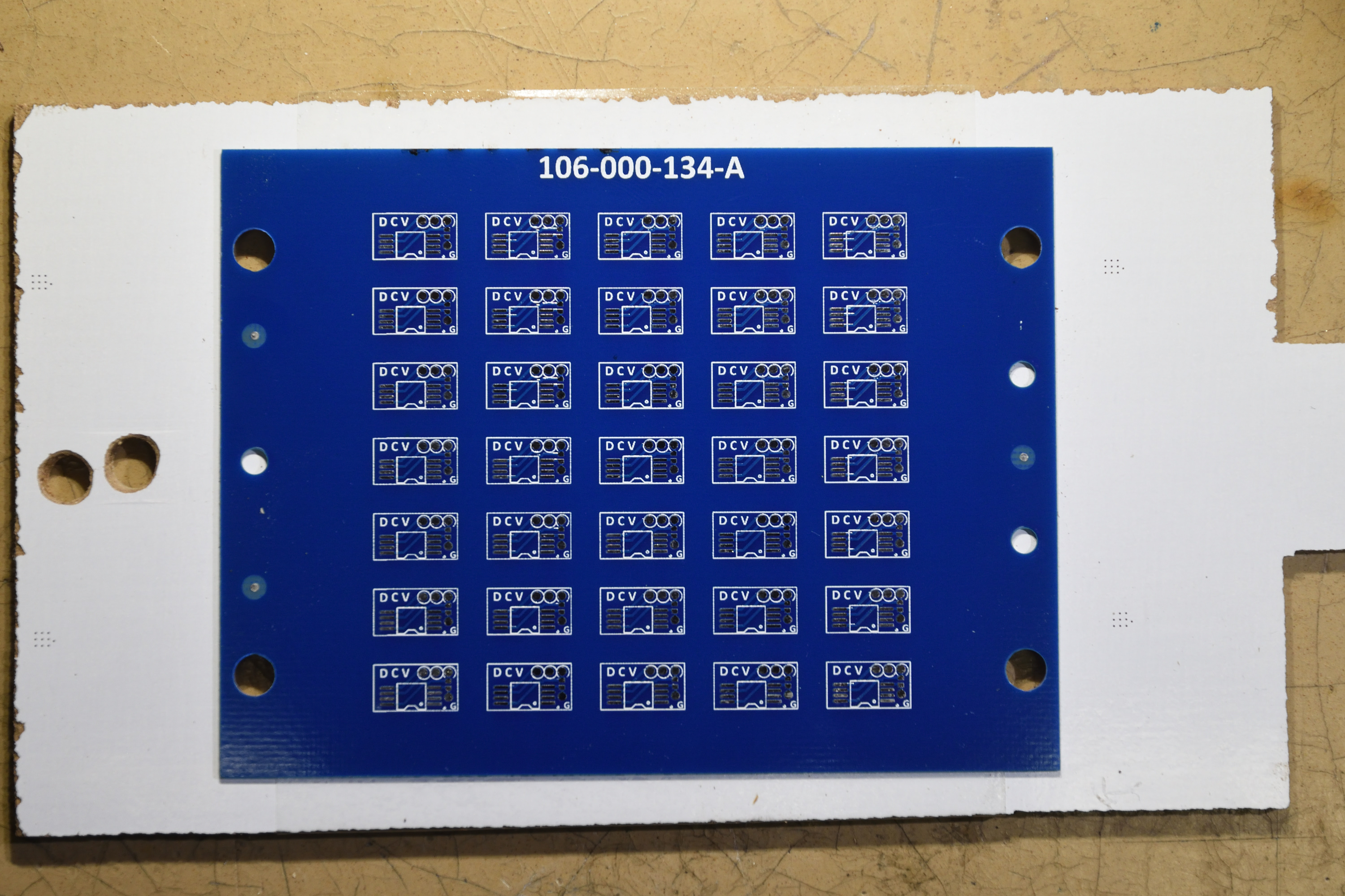
I tried to separate the PCBs on another panel using the CNC mill. Here is the report on how I did it (so that I remember until next time).
The first step is to have a CAD drawing in DXF format of at least where the center lines of all the cuts shall go. It is not obvious how to best lay out these lines. Should one go for fully separated PCBs? Or should one leave bridges between them to avoid the problem of PCBs (maybe) flying around as soon as they are separated, but with the problem of not getting fully separated PCBs in the end?
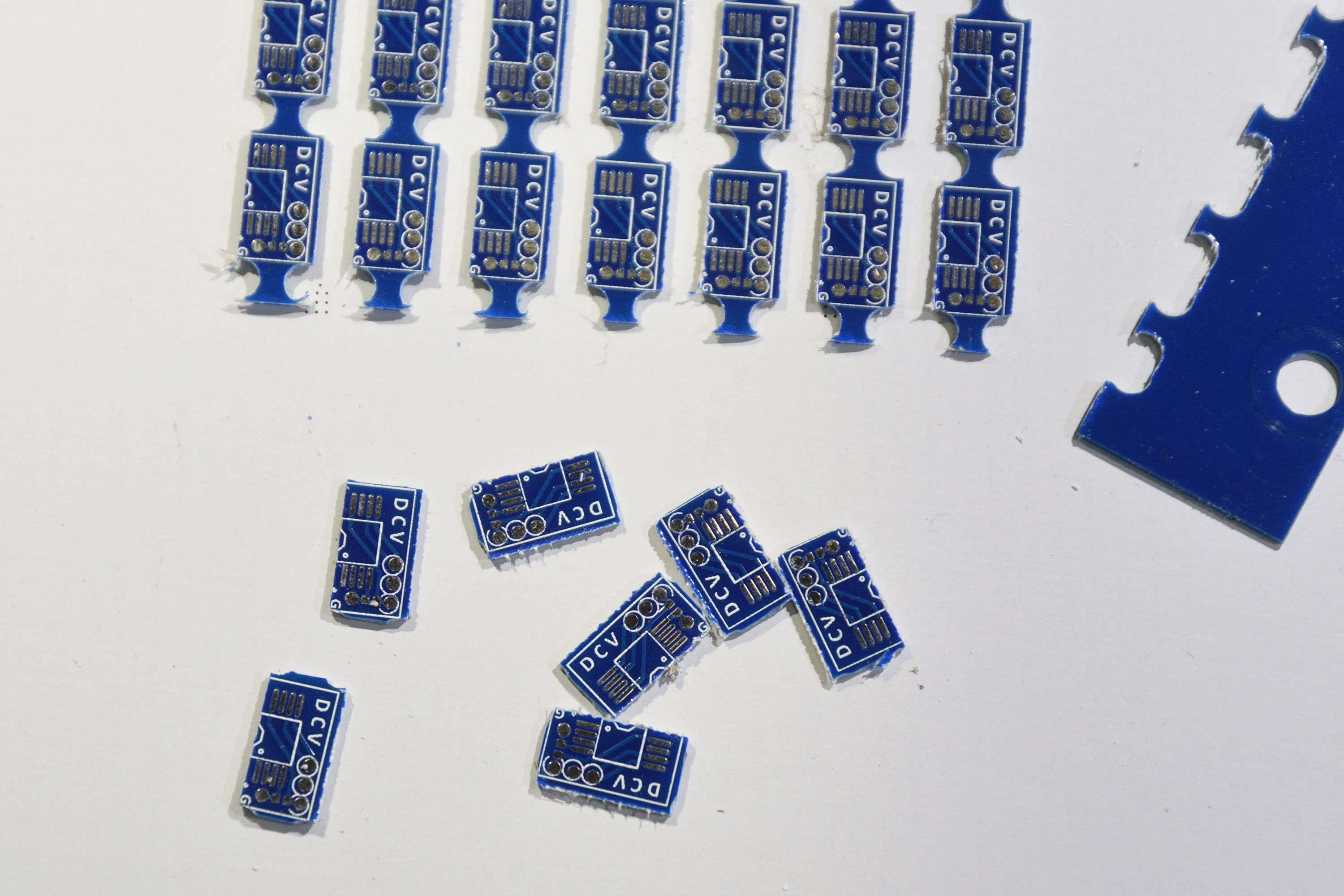
This time the PCBs were super-small, only 10.5 mm x 6 mm, so I decided that the holding force of the double sided tape would probably not be strong enough to securely keep the PCBs in place. Therefore I opted for only partial depanelization by milling. Since the thickness of the PCBs in this case was only 0.6 mm, I could use scissors for the final step. In fact, I could have exclusively used scissors and not involved the mill at all, but that would not be as fun. And one could argue that that would have resulted in more warping and strain on the PCBs.
To define the mill pattern, I exported data in DWG format from the CAD program (Altium) and opened it in DraftSight where I made some adjustments. After this, the CAD files contained the center lines of the mills, the board outline and the outlines of the holes in the panel. I then saved it as a DXF-file, as Fusion 360 (where I create the G-code program for the mill) does not seem to understand DWG.
In Fusion 360, I started a new sketch and used the command INSERT -> Insert DXF to import the CAD file.
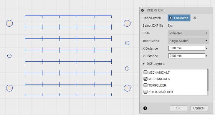
Here one can select which layers to import and what units to use. In my case I only needed the data on layer MECHANICAL8 and the units were (of course) millimeters.
When the data is in, one does not have to do any more work in the MODEL section of Fusion 360, but there is more to be done in the CAM section.
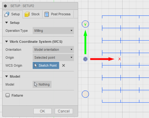
Add a new setup (SETUP->New Setup) and make appropriate selections. One important thing is to define the origin in a clever position that is easy to identify and calibrate on the mill. For this purpose I had placed a 3 mm hole in the panel which I intended to locate using the 3 mm end mill needed for the depanelization (2 mm would probably have been a better idea, but I do not currently have a suitable 2 mm end mill). For some reason, Fusion 360 refused to select the center of the 3 mm circle as the origin until I first placed the origin at the end of a mill line and then retried to select the circle. Weird bug.
In the Stock tab of SETUP I selected Relative size box, No additional stock and Round Up to Nearest 1 mm. This is probably unimportant since there is not even any 3D body defined, so Fusion 360 thinks the model has zero size.
In the Post Process tab, I added a suitable Program Name and Program Comment (helps with default file name and comments in the G-code).
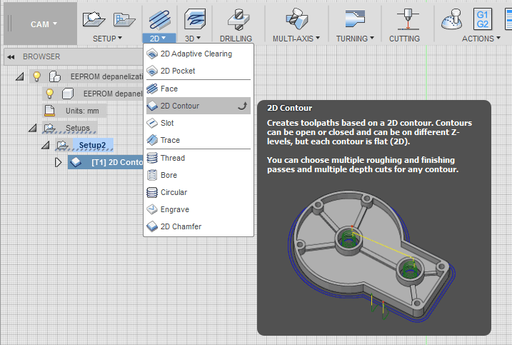
The main trick is to use 2D contour with Compensation Type set to Off as the milling strategy in order to let the center of the mill follow the center of the lines in the drawing. This is done by 2D->2D Contour:
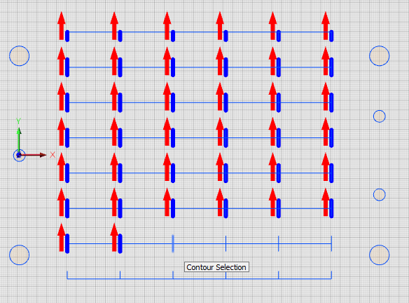
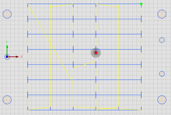
I selected the appropriate tool in the first tab (in this case a 3 mm end mill) and in the second tab I selected all the vertical segments. This is a bit tedious since drag-select does not work. The reason I only selected these segments and not the horizontal ones, is that I want the panel to stay as rigid as possible as long as possible:
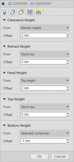
In the third tab, I define the heights. I generally decrease the clearance and retract heights to make the machining faster. I let the Top Height be 0 mm from Stock top and set the Bottom Height to -1 mm from the Selected contour(s) (Stock top would also have worked). This defines that the tool will go 1 mm deep (when I zero the mill on the top of the PCB), which is enough since the PCB panel is 0.6 mm thick.
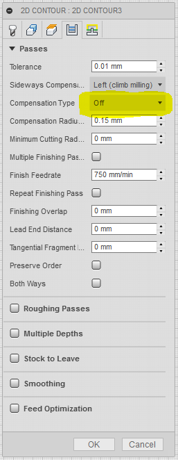
The fourth tab is very important. This is where Compensation Type shall be set to Off so that the center of the mill tool is not offset from the lines:
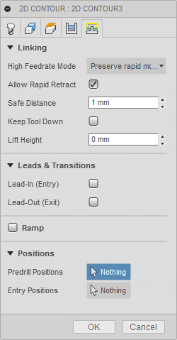
The fifth and final tab is also somewhat important. Here we need to untick the Lead-In and Lead-Out boxes to avoid undesired lateral movements of the mill that would ruin the PCBs. I also unticked the ramp box and let the tool plunge straight down:
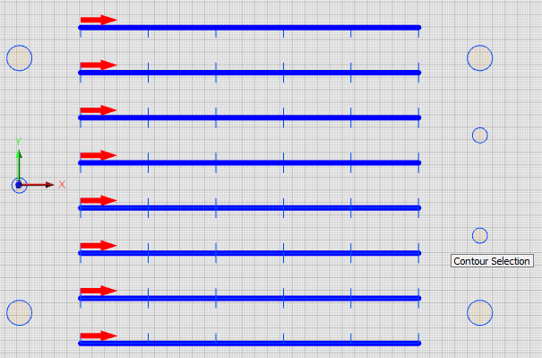
After clicking OK, the following tool path (yellow) was generated:
Fusion 360 reorders the segments in some more or less optimal order. The order in which the segments were selected does not seem to matter.
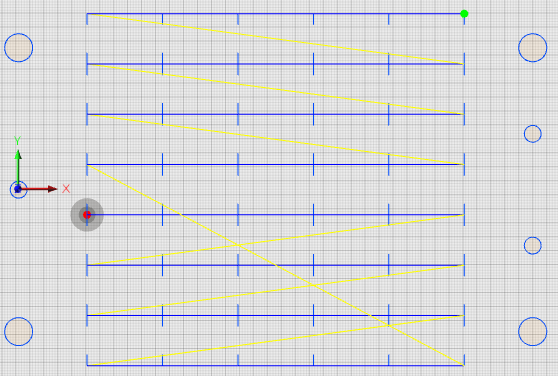
Duplicate the operation (to avoid a lot of repetition of settings), clear which segments are selected and select the horizontal lines:
The resulting tool path looks like this:
As I mentioned, the reason for having two operations is that I wanted to mill the short segments first (to keep the panel as rigid as possible as long as possible) and with a single setup, it is impossible to control the order of the milling.
To generate the G-code, click on the Setup containing the two milling operations (so that not just one of the milling steps is selected) and then select ACTIONS->Post Process.
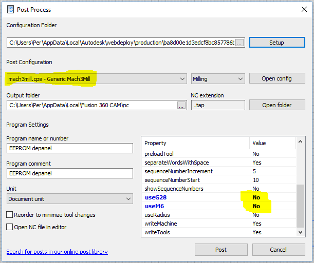
Fusion 360 has an irritating habit of forgetting the post processing settings when it updates itself. This results in the following error message:
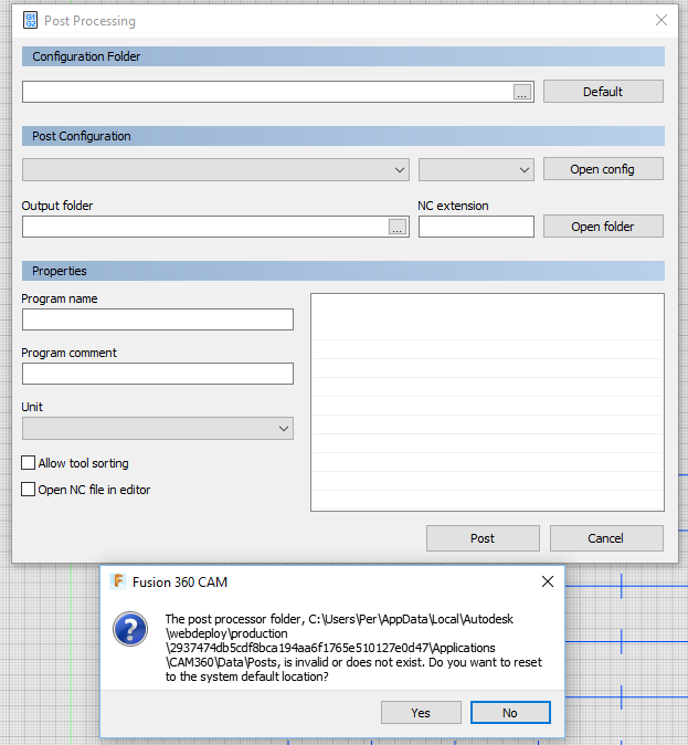
Since the previous configuration has been forgotten, I have to tell it again that I do indeed have a Mach 3 mill and (very importantly) that it should not use the commands G28 and M6.
After the G-code has been generated (by clicking Post), it is finally time to set up the mill to do the work. I had designed the panel such that it had four 5 mm holes that fit with the T-slots of the milling table. I drilled corresponding holes in a piece of sacrificial MDF board and placed double sided tape on the board:
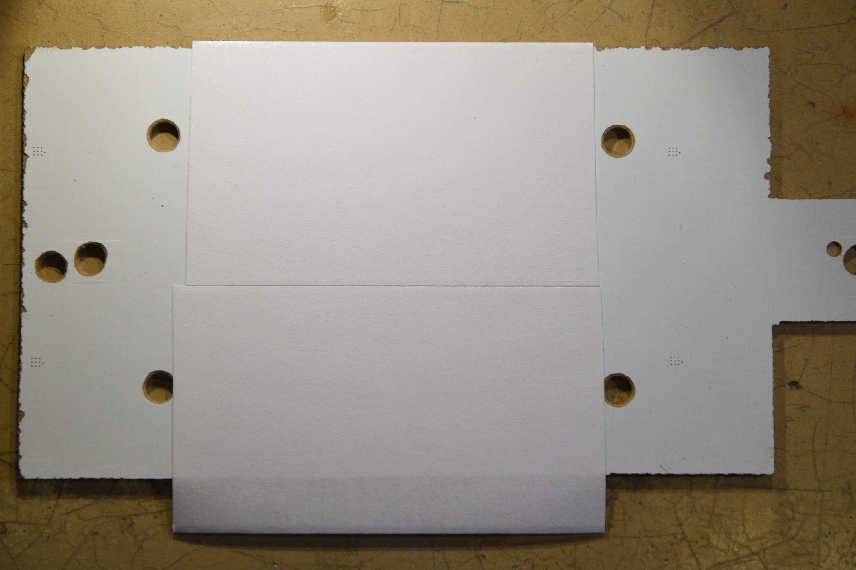
I then put down the PCB panel on the tape:
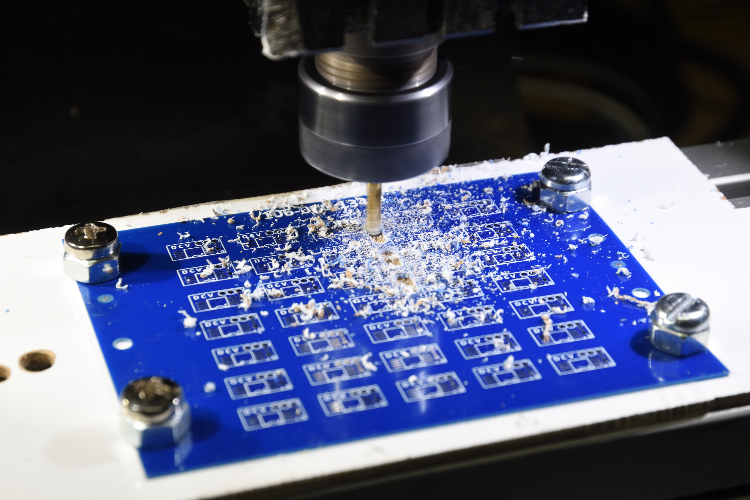
It is then time to screw the panel to the table while making sure the panel edge is very parallel to the table. I had to use oversize (M6) nuts under the heads of the screws to make them fit with the T slots:

I manually moved the mill precisely to the 3 mm hole on the left edge of the panel and zeroed the coordinates. Then it was time for action:
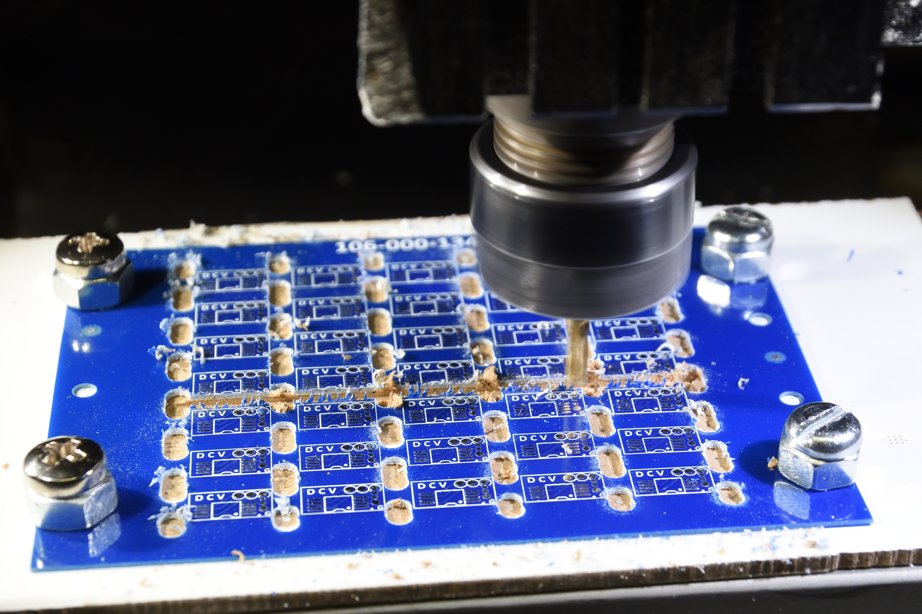
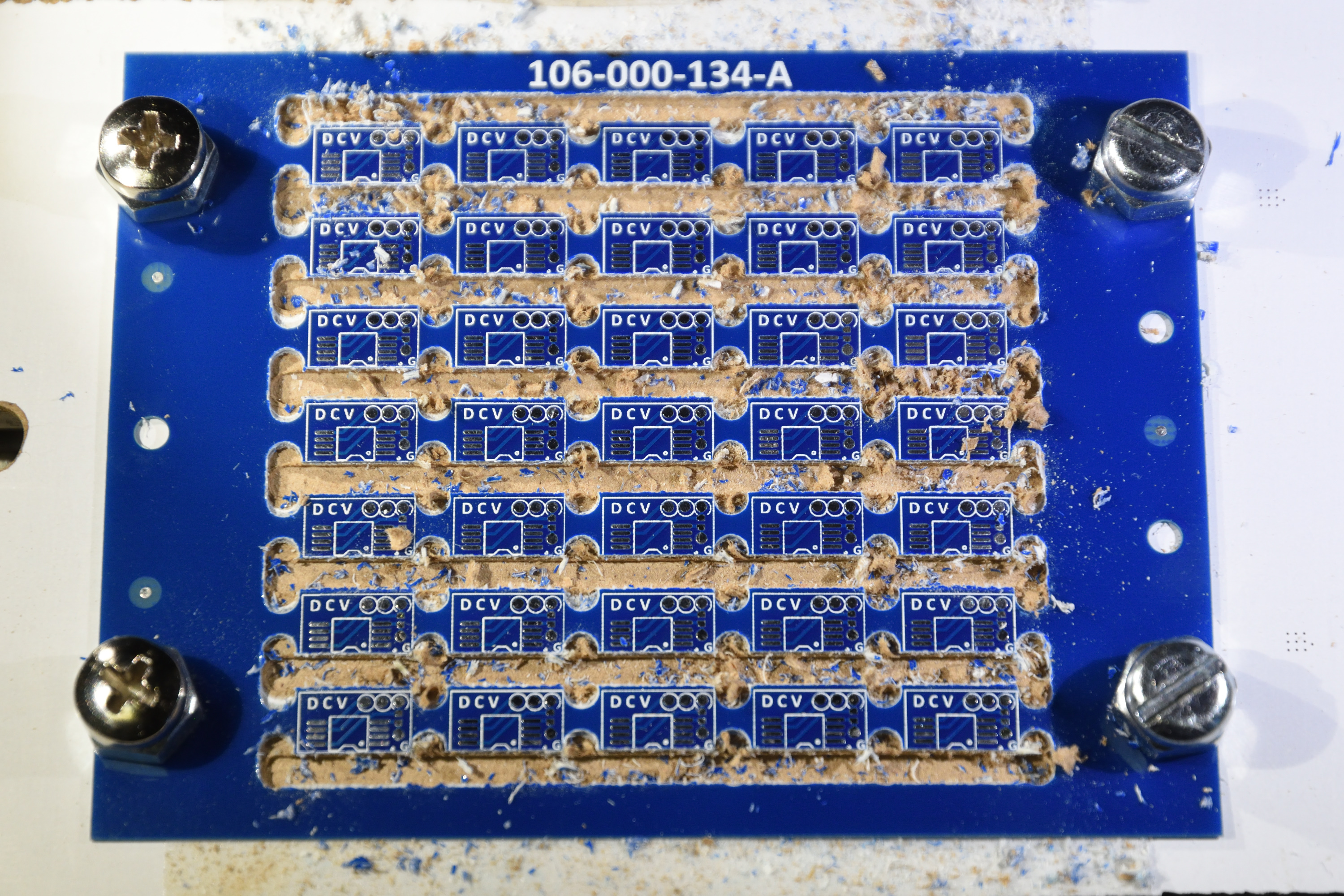

The result is acceptable, but not perfect. There are some burrs, which may have been caused by the end mill not being as sharp as it should have been. At first glance there seems to be a bit of mis-registration of the milling compared to the PCBs, but at least some part of this is actually mis-registration between the overlay print and the copper. Compared to the copper, the milling seems to be very well positioned.
An idea for future improvement that I have is to not just leave a bridge between boards, but make this bridge thinner by milling down partially through the laminate. Maybe one can get away with leaving 0.3 mm or so of the material. This would make the scissor cutting easier. It is probably best to make these partial depth mill cuts first when the tape is pristine and let the full depth cuts (which can tear the PCBs somewhat loose from the tape) follow later.