Combining electronics and photography can be quite fun. Here is a description of a mini-project I did recently.
I have some magnetic putty that I wanted to take time lapse video of. I also have a digital still camera (Nikon D300) and a manual remote shutter release with 2.5 mm stereo jack connectors. There are remote shutter releases with time-lapse functionality built in, but this was not present on mine, so instead I decided to create the time-lapse functionality by means of an Arduino Nano. (After almost completing this post, I realized that there is in fact a shutter release timer feature in the D300 menus. Duh! So I could have used that if I had settled for having the same time between each pair of exposures.)
Interfacing to the camera is quite simple. Two open collector outputs are needed, one for pressing the shutter release button halfway (to focus) and one for pressing it all the way down to take the picture. Some experimentation showed that it is necessary to first emulate pressing the button halfway and then release the shutter. It did not work if the halfway step was skipped.
It would probably be possible to use Arduino pins directly to talk to the camera by switching the pins between tri-state (button not pressed) and low (button pressed), but I decided to use external transistors to ground the signals instead as shown in the schematic below.
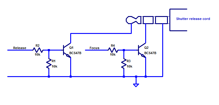
The signals Release and Focus go to Arduino pins.
In addition to the camera control signals, I added a power MOSFET connected to another Arduino pin in order to control LED lighting. This might be useful when the period between pictures is very long to save power and prevent the LED from getting unnecessarily hot. In the end I did not use this feature as I suspect it might contribute to somewhat varying light intensity between shots which would appear as flicker in the resulting video.

Some code is of course also necessary. I decided to control the operation via the USB cable using the serial monitor. Since the process I intended to film tended to have the most action at the beginning, I made the intervals between the exposures longer and longer. This kind of feature is perhaps not so easy to get from a commercial remote release timer.
The functionality is very rudimentary and the code should be pretty self explanatory with the few comments that are included.
Capturing the series of photos
So, now we have the hardware and software to capture the time lapse photos. What is next is to set up a little photo studio where the action can take place and configure the camera. There are a number of things to consider in this process. Here are some that I figured out:
- Make sure you have a freshly charged battery in the camera and enough space on the memory card.
- Even HD videos have much lower resolution than still images from DSLRs. To limit the amount of data you will have to deal with, set the resolution to the smallest value bigger than the resolution you want your film to be. Also, it is probably good enough to select the lowest JPEG quality that the camera supports to further minimize the size of the image files. The video compression is anyway likely to be the limiting factor rather than the quality of the JPEGs.
- Lighting is important. I used a single LED desktop lamp, but I replaced its power supply by a bench supply to make sure there was no flicker from the mains. Light sources that flicker with the mains frequency are actually probably OK to use provided the exposure time is an integer multiple of the half period of the mains. In Europe the mains period is 50 Hz, so the half period is 1/100 s. This means that exposure times like 1/100, 1/50, 1/25, 1/10 etc are OK, but not e.g. 1/60 or 1/200.
- To further prevent the light from flickering in the video, it is pretty important to shield off any uncontrolled or variable light sources, like light from a window, a computer screen, lamps that might be occluded by you walking by etc. The ideal case is probably to have the setup in a windowless room where the only light sources are the ones you intentionally use to illuminate the subject.
- Since you will probably be shooting in JPEG (not raw), it is important to set the white balance correctly. Do not set it to auto.
- Put the camera on a tripod.
- Compose the scene such that your subject will stay inside it during the action. Consider that you might want to crop the pictures to 16:9 which is a common video aspect ratio. This means that you will lose some of the top and/or bottom of the field of view.
- Use auto focus to get the focus right, but then switch over to manual focus. You do not want the camera to try to refocus for every exposure.
- You probably want a small aperture, perhaps between f/10 and f/22 to get a large depth of field since the subject might move away from or towards the camera during the filming and you do not want it to get out of focus.
- Set the camera on manual to peg both aperture and exposure time so that they do not change between shots. That would otherwise result in flicker in the video.
- Take a picture manually to see that it looks fine in terms of exposure, composition, white balance and focus.
- Perhaps you want to turn off preview on the camera display to save battery. On the other hand it might be useful to be able to preview what the camera sees during the shoot.
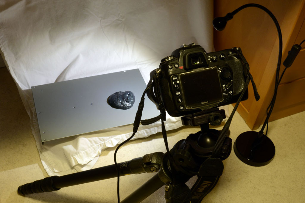
Below is a photo of my make-shift setup under a desk.
When all is set up properly, it is time to start the interval timer by giving the proper command in the serial monitor and then just wait until all the action has been captured.
I will describe how to make a video based on all the JPEGs in the next post.
Hi there,
I know this post is 2 years old so I hope you’re still monitoring this. I’m trying to do a similar thing without the arduino but just the 2.5mm 4-pin plug to a 2.5 female jack and connect it (tip and sleeve?) directly to the signal pin of a 360 servo on my diy slider to do shoot-move-shoot timelapse and night sky moving timelapse. I will still be using the camera’s built-in intervalometer to time the shots together with the remote doing the move commands. I haven’t received the shipment of 2.5mm female jacks to start making connections so I want to ask you if this scheme would even work. I have seen it work from a post on youtube but my first attempt was not successful with the Neewer brand remote that had a 3-connector 2.5mm plug, which worked straight to the camera but not on the servo circuit. Eventually it stopped working with the camera altogether and had it sent back to amazon. Now I have a new remote which works direct to camera and will hook up to the servo when the female jacks come. The appeal of this scheme is i won’t have to deal with the arduino because of my limited knowledge on the subject. So do you see this working without the arduino, just straight to the servo from the timer release? Your response and opinion would be greatly appreciated…Ron SanAgustin
Hi Ron,
I am not sure I follow your description. What is controlling what? Why do you need the remote shutter release cable if you use a built-in intervalometer of the camera?
Per