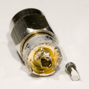
A couple of weeks ago, I was using an ANNE-50+ 50-ohm SMA termination from Mini-Circuits, but noticed that it did not seem to work right. When I measured it using an ohm-meter, the resistance was around 100 ohms instead of the expected 50 ohms. I put the termination aside and I just got around to taking a better look at it since I was curious about how it was constructed inside. Below are two photos of what the termination looks like.
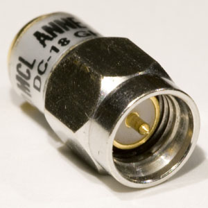
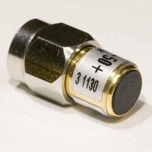
ANNE-50+ termination
Before I started taking it apart, I remeasured the resistance. This time it was no longer 100 ohms, but rather an open circuit. So something had apparently happened inside it, although I am certain that it was not used while waiting for the autopsy.
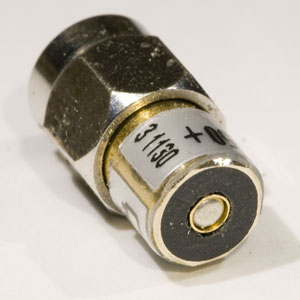
Then it was time to start uncovering the secrets of the termination. I began by filing down the back side of it, which consists of a black plastic cap inside a brass tube.
Less than a mm below the surface, some more metal was revealed in the center of the device. This metal turned out to be electrically connected to the outer shell (ground).
Further filing next to the central metal piece allowed the plastic to be removed, revealing a 360 degree low-inductance metal connection between the center stud and the shell.
Going a bit further allowed the central stud to fall out. It turned out to be a (cracked) resistor. It seems to be either a carbon film or metal film resistor on a ceramic core. The fact that it has somehow become cracked is of course the reason the device failed in the first place.
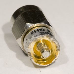
A few final strokes with the file allows the remains of the pressed-in metal piece that connected the resistor to the connector shell to be easily removed. The center pin of the connector with its (teflon?) insulation and the other end of the broken resistor also easily falls out after this. The different pieces are shown in the photos below.
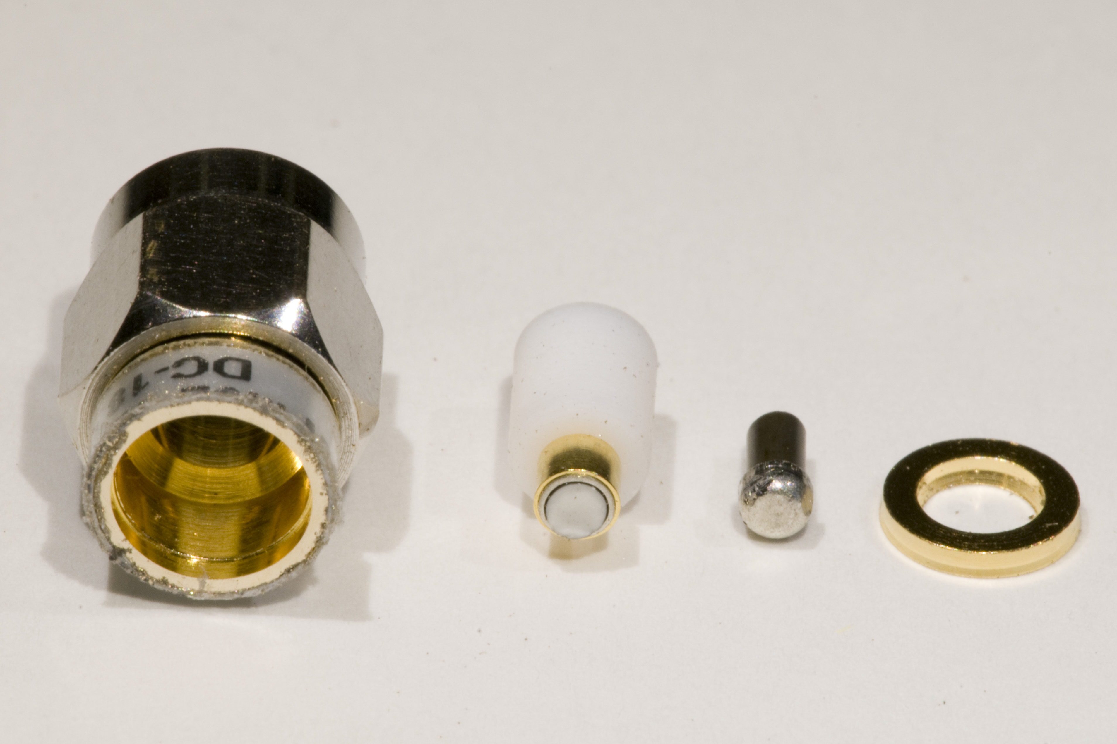
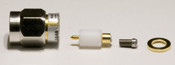
One can see that the diameter of the hole in the shell of the termination is different in the section with the connector pin and the section with the resistor. The first diameter is dictated by the dimensions of the SMA connector and is almost certainly designed to give a 50-ohm impedance with the pin diameter and the dielectric used. The second diameter might be chosen to give the best possible return loss given the dimensions of the film resistor, but it might also be chosen primarily for mechanical convenience.
This termination is specified to have a return loss of better than 21 dB up to 18 GHz. I have heard that some other terminations which are not specified to perform well up to such high frequencies use standard SMD resistors inside, but performance to 18 GHz probably benefits from the coaxial design of this device.
So what might have caused the failure of the termination? I do not know for sure, but since the center pin is largely held in place by the apparently brittle body of the resistor, it seems like a strong force or torque on the center pin is the probable cause. This might have occurred because the termination was mated to a damaged SMA connector or for some other reason.
One thought on “The Anatomy of a (Broken) Termination”