Update 2023-03-14: Phillip D., yildi1337, has implemented the noise sources described in this blog post in easy-to-use, parameterized LTSpice components. The components are available in the following Github repo: https://github.com/yildi1337/LTspiceNoiseSources.
Update 2019-03-14: As Jason pointed out in a comment, the simulations below involving Laplace sources do not directly work in LTspice XVII. The reason seems to be that LTspice changed its behavior such that it now (incorrectly) considers nodes connected to ground via the kind of behavioral current sources used here to be floating. To remedy this without affecting the simulation results, a very large resistor (e.g. 1 GΩ) can be inserted between such nodes and ground.
There does not seem to be a direct way of adding a voltage noise or current noise source to an LTspice (or other kinds of Spice for that matter) circuit to be used in a .noise simulation. It is however possible to add noise sources to be used in .tran (time domain) simulations using behavioral sources, but this is not what this post is about. Instead it shows a method of adding white (Johnson as well as shot) and 1/f (flicker) voltage or current noise sources of the desired amplitude to be used in .noise simulations.
One case where such noise sources can be useful is when making simulation models of amplifiers (like opamps) where the input referred voltage and current noises are known from the datasheet.
The only simple noise source (that affects .noise simulations) in LTspice is a simple resistor. Other noise sources exist in semiconductor device models, but those models are more complex and messy. An ideal resistor has a voltage noise described by:
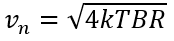
Where k is Botzmann’s constant (1.381×10⁻²³ J/K), T is the temperature in Kelvin (300 K by default in LTspice), B is the bandwidth in Hz and R is the resistance in Ω.
A datasheet for an amplifier typically specifies the white voltage noise in units of nV/√Hz and current noise in fA/√Hz (sometimes pA/√Hz).
So, can we somehow create noisy voltage and current sources based on noisy resistors? The answer is yes, by using dependent sources. To create a white voltage noise source, we can connect the input terminals of a voltage dependent voltage source (E source) to a resistor and use a suitable scaling factor. The dependent source isolates the resistor from any circuitry that is connected to it and preserves the voltage noise amplitude regardless of load.
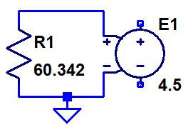
As mentioned above, the noise source we are trying to model is usually specified in nV/√Hz, so it would be convenient to be able to directly enter that number as part of the model. A simple way of doing that is to select a resistance that produces a noise density of 1 nV/√Hz and enter the noise amplitude from the datasheet as the voltage gain of the dependent source. Solving the above equation for vn = 1 nV when T = 300 K and B = 1 Hz gives R = 60.343 Ω.
The resulting LTspice schematic for a 4.5 nV/√Hz voltage noise source is thus:
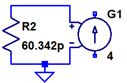
Similarly, to create a white current noise source, we can use a voltage dependent current source (G source). To allow us to set the transconductance factor of the source to the noise density in fA/√Hz, we need a resistor with a noise density of 1 fV/√Hz, which means that the resistor shall have the very small value of 60.343 pΩ (piko ohm)! A current noise source with a noise density of 4 fA/√Hz can thus be modeled like this:
Often, one is also interested in flicker noise, whose power density is proportional to 1/f, i.e. it decreases with frequency. If the power density is proportional to 1/f, the voltage (or current) noise density is proportional to 1/√f. This makes it a bit harder to create a model for this kind of noise in LTspice, but it is still possible. The trick is to use the white current noise source above and connect it to a behavioral current source (B source) which has a Laplace function that makes it behave like an impedance whose magnitude is 1/√f. I found the documentation to be a bit unclear on behavioral sources, but after some experimentation I got the following to work:
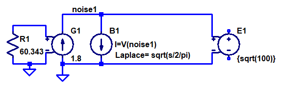
The documentation for a behavioral source in LTspice says that “If an optional Laplace transform is defined, that transform is applied to the result of the behavioral current or voltage.”. It seems that applied in this case means divided by. Unexpected in my opinion.
So the way this B source works is that it produces a current that is the same as the voltage across it (divided by an implicit resistance of 1 Ω to get the units right) and this current is modified by dividing it in the Laplace/frequency domain by the Laplace expression √(s/2π). The complex frequency variable s of the Laplace transform can be written as s = σ+jω = σ+j2πf where f is the frequency in Hz (and σ is the hard-to-interpret real part of s, which can be set to 0 to essentially convert the Laplace transform into a Fourier transform). By dividing s by 2π, we get the desired behavior of an impedance whose magnitude is equal to 1/√f. This impedance is not a pure resistance, but a complex impedance that will cause a phase shift of 45 degrees between current and voltage. Phase shifts are however irrelevant when dealing with noise (unless there are multiple signal paths from a noise source to a node) and the important thing here is that the magnitude of the impedance is right. If we wanted to model a resistor with a resistance of 1/√f, we could divide s by √-1 to make the impedance real, like this: Laplace = sqrt(s/2/pi/sqrt(-1)). This would work equally well in our model for flicker noise, but the expression is bigger and clumsier without changing the noise simulation results.
The level of flicker noise is typically given in one of two ways in datasheets. Either one can read the level off a graph at some frequency where the flicker noise dominates, or it is specified as the corner frequency fc at which it is equal to the white noise level at the same node. In both cases we know the noise level at some frequency and we would of course like to be able to input these two numbers into the noise generator model. This is done by setting the noise level (at the specified frequency) as the transconductance of the G source and by setting the gain of the E source to the square root of the specified frequency. The reason we need to use the square root of the frequency is of course that the white noise current from the G source is multiplied by 1/√f by the B source and that we want to scale it back up to the same intensity precisely at fc. Multiplying the noise by √fc obviously cancels the 1/√f factor at fc.
A flicker current noise generator can be created in a very similar manner. The only difference is that the output is produced by a G source and that the noise generating resistor is 60.343 pΩ. Here is an example:
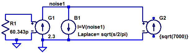
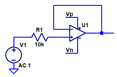
So let’s put all of this together and create a noise model of an opamp connected as a voltage follower like this:
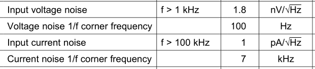
As an example, I selected OPA838 whose datasheet contains the following noise specifications:
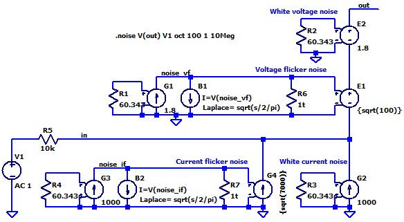
Here is the resulting noise model with all four noise sources (and 1TΩ resistors to make LTspice XVII happy):
Link to the above LTspice schematic
The white current noise is 1000 fA/√Hz (R3, G2) and the current noise corner frequency is 7000 Hz (R4, G3, B2, G4). The white voltage noise is 1.8 nV/√Hz (R2, E2) and the voltage noise corner frequency is 100 Hz (R1, G1, B1, E1).
The 10 kΩ source resistor R5 is not part of the noise model of the opamp input itself, but is the impedance of the circuit driving the opamp input. This resistor converts the current noise into a noise voltage at the opamp input.
The out node is actually the non-inverting opamp input in this model.
A quick look at the circuit reveals that the 1 pA/√Hz times the 10 kΩ input resistor results in a noise voltage of 10 nV/√Hz, which will dominate over the much smaller 1.8 nV/√Hz white voltage noise.
Here are the simulation results from LTspice:
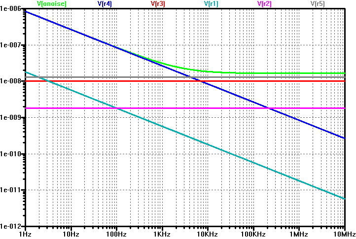
The green curve is the total noise at the out node, flattening out at around 16 nV/√Hz at high frequencies. The other curves show the individual contributions from the various noise sources. Below 4 kHz, the current flicker noise (R4) dominates and above that the noise from the source resistor R5 is the largest contributor, closely followed by the white current noise (R3). In this circuit, the voltage noise sources R1 and R2 have negligible effect and even the white current noise source contributes less than what the source resistor does, so it is only below ~4 kHz that the opamp noise (in particular the current flicker noise) becomes dominant in this application. The very good voltage noise specification of OPA838 is of little value with this high a source impedance.
Outstanding blog post. This is tremendously helpful.
Excellent tutorial. Bookmarked for future and frequent reference!
Thanks so much for sharing such a valuable tutorial. I really appreciate your wonderful explanation.
Thank You Very Much.
It does not work for me
I am just trying the white noise voltage source
60.343 resistor & VCVS
I always get zero volts or current ouputs
I am runing transient simulation
any suggestions?
Thank you
Fausto
Hi Fausto,
As I mention in the heading and in the first paragraph of the blog post, this is about noise sources for .noise simulations, not for .tran simulation. You might be able to use behavioral sources to emulate noise in .tran simulations to be able to study noise in the time domain, but this is something I have not looked into.
Per
When it comes to .noise simulation it works perfectly fine.
I know this is not meant for .tran simulation but I have been scratching my head for few days on how to implement flicker noise to an already existing system and study its effect in the time domain.
Is there any way how to try and implement this for .tran simulation?
Hi, did you find the way to implement flicker noise for .tran simulation
?
Hi, my simulation does not work. The simulation states that the nodes of noise_if and noise_vf are left floating. I used the file exactly as downloaded. Any ideas?
Hi Jason,
Thanks for reporting this. In earlier versions of LTspice, this was not a problem, but apparently LTspice XVII thinks the nodes only connected to GND via a current source and a behavioral current source are floating. They really are not in this case, so this seems like some kind of bug.
A workaround is to connect very large resistors between the “floating” nodes and GND. I tried with 1 tera-ohm resistors and this did the trick. I have now updated the blog post accordingly.
Per
Hi, shouldn’t the 1 TOhm resistors be “noiseless”?
Hi Nur,
In principle yes. However, in practice it makes no difference. The noise current from such a resistor is sqrt(4kTB/R). With an R of 1 Tohm in the denominator, this current is truly insignificant. This is easy to show if you just plug in the numbers for the contribution in the part of the spectrum where the white noise is dominating (in the 1/f-region the contribution is even less significant).
Per
Thank you for a brilliant model and a very good article!
I am testing different ways to model noise from parameters from datasheets and when it comes to flicker noise it is often the case that the parameter given is the peak-to-peak value over some low bandwidth (typically 0.1 to 10 Hz). I have found that the noise plots often lack the detail to be able to get a good noise value where flicker noise dominates.
So my question is, do you have any ideas on how I could adapt your approach for flicker noise so that it can take a peak-to-peak value and a bandwidth and get it to produce that as flicker noise?
Hi Jesper,
Which opamp are you thinking of? In my experience, it is less common to just have the peak-peak LF noise than a plot showing the voltage noise as a function of frequency. From such a plot, the 1/f knee frequency can be visually determined, even if it is sometimes made a little harder by a linear scale on the Y axis.
It seems like a tricky problem to derive the perfect mathematical relationship between the peak-peak noise observed over 10 s in a bandwidth from 0.1 to 10 Hz, and the level of the 1/f noise. In principle it should be doable, but it seems much easier to take a pragmatic approach and check the relationship for a couple of opamps where the data is available.
If we assume 0.1 – 10 Hz is totally dominated by 1/f-noise, there should be just a simple universal factor to get from peak-peak voltage (e_npp) to the spectral density measured in nV/rtHz at e.g 1 Hz. Here are some examples:
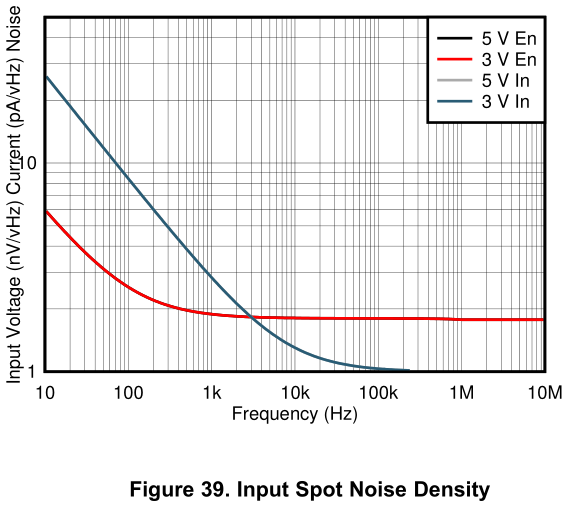
For OPA838, e_npp (taken from Figure 40) is 120 nVpp and the spot noise at 1 Hz e_n1Hz (extrapolated from figure 39) is 19 nV/rtHz, giving a ratio of e_n1Hz/e_npp of 0.16.
For ADA4075-2 supplied by +/-15 V, e_npp = 60 nVpp and the noise at 1 Hz is 9 nV/rtHz. The ratio is thus 9/60 = 0.15. Nice. Very close to the previous result.
For AD8615, the numbers are 2100 nVpp (or 2400 nVpp?) and (by extrapolation) 220 nV/rtHz, giving a ratio of 0.1 or 0.09. Not so close any more…
For LT1782, we have 1 µVpp and 76 nV/rtHz@1Hz, giving 0.076, but here the 1/f knee is so low that there is a significant contribution from white noise to the peak-peak value, so maybe we can ignore this…
These are the first four opamps with usable data that I happened to find. The variation from 0.09 to 0.16 in the factor between peak-peak LF noise and 1/f spectral density at 1 Hz might indicate that the method is in theory somehow flawed (although I do not see how), or perhaps that the peak-peak measurement is not defined well enough to be reliable to within better than perhaps +/- 50%.
Let me know if you dig deeper into this and find out more.
Really great tutorial. Especially with regards to using a real part with NSD graphs to compare against.
I had some similar problems with the flicker noise model as a cascade of current generators. However the Voltage-Dependent-Voltage-Source (E directive) also allows Laplace, although I couldn’t get it to understand pi as a constant. Another bug it seems.
Thanks again.