Electronics for the Lapse Pi Motorised Time-Lapse Rail

A friend of mine is building a Lapse Pi motorised time-lapse rail and she asked me if I could make the required electronics. A time-lapse rail allows you to take time-lapse sequences during which the camera moves a short distance between each shot for artistic effect.

The electronics is not particularly complicated. A DC/DC converter is needed to convert the battery voltage of 12 V to 5 V for supplying the Raspberry Pi and then a few transistors are required to control the motor and the camera shutter.

DC/DC converter

The most complicated part is the DC/DC converter. Since I was only about to build one unit, I decided to try to minimize work, possibly at the expense of a non-optimal design in other respects, but still with decent power conversion efficiency. A linear regulator was out of the question as the efficiency in going from 12 V to 5 V is at most 5/12 = 42 %, so a more complicated switching DC/DC converter was clearly required.

I decided to buy a cheap car cigarette lighter to USB adapter which does the job of converting a voltage in the range of 12 to 24 V to 5 V to do the job. Good since it did not require any design work on my behalf. Or so I thought.
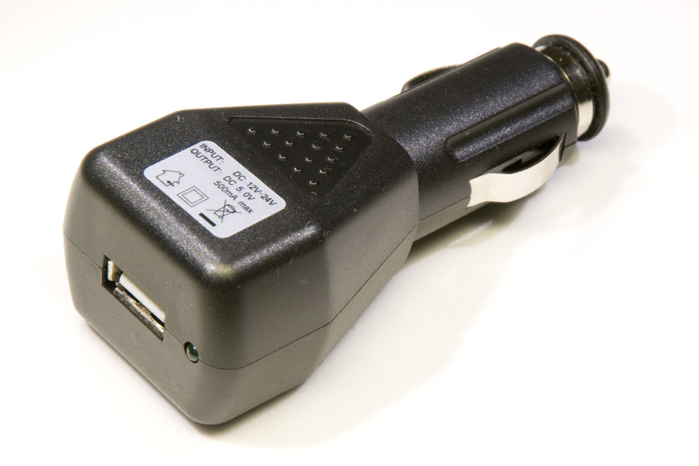
Cigarette lighter to USB adapter

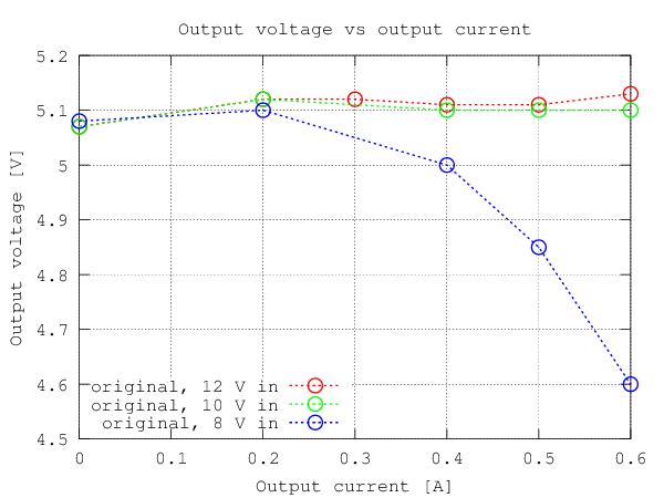
What I should have done is to check the power requirements of the Raspberry Pi. I somehow had assumed it could be driven by the current nominally available in a single USB port (500 mA), but it turns out that it needs 700 mA according to the schematics and 500 to 1000 mA according to this FAQ. The car-to-USB adapter I had bought unfortunately turned out to be designed with very little margin (not too surprising for a cheap consumer product). It started making an alarming whistling noise when the current exceeded 500 mA and for lower input voltages (like 8 V), the output voltage started dropping even at 400 mA. Ooops. Below is a plot of the output voltage vs output current for three different input voltages.
Output voltage plot
Output voltage vs output current for a few different input voltages.

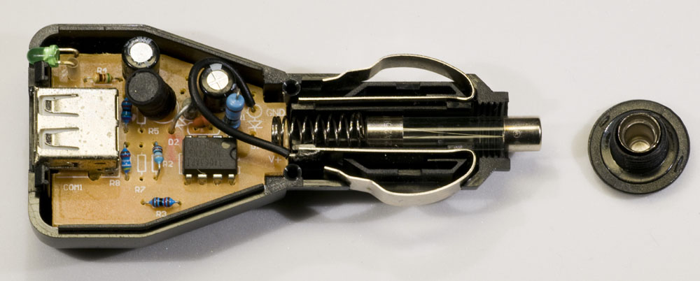
So, what to do? I took the converter apart to see if it were possible to modify it to make it more powerful. Inside I found a small PCB, see photo below.
Innards of 12 V to USB adapter

The circuitry is based on an MC34063A, which is a rather old and simple DC/DC-converter chip made by e.g. Texas Instruments and ON Semiconductor. The way it was connected in the product was almost exactly like the step-down (buck) converter schematics given in figure 11 of the datasheet. The chip itself has a switch transistor that is able to handle 1.5 A, so this is not what limits the output current. Unfortunately, the transistor is an NPN darlington, so it has a fairly high voltage drop resulting in low efficiency, especially for low input voltages, so heating could be a problem for high output currents.

The component that primarily limits the available output current is however the inductor. It is relatively small and unlabeled (the black cylindrical component right above the text R5 in the picture above). I desoldered it and measured the inductance which turned out to be around 160 µH. This is smaller than the recommended value of 220 µH in figure 11 of the datasheet. I did not have any simple way of measuring how the inductance changed as a result of increased current, but it is very likely that the inductance starts to drop off significantly as the current reaches 500+ mA (there is a ripple current on top of the average output current that the inductor has to handle).

Replacing the inductor with a bigger one with smaller ESR (equivalent series resistance) and suitable for maybe 1.5 to 2 A and perhaps with a somewhat higher inductance seemed like a good modification to the circuit. But the NPN darlington also looked like it was in need of some improvement. Figure 12 of the datasheet shows how an external PNP transistor can be connected to boost the output current. An advantage is that the transistor can saturate and thus have a very small voltage drop (maybe 0.1 to 0.3 V or so) when it is on, which is good for efficiency. Power PNPs are however not know for their high current gains, so efficiency suffers due to all the wasted base current that is needed to reliably saturate the transistor.

It seemed like a modern PMOS transistor would be a better choice as it can have a very low on-resistance and not require any base (gate) current to keep it on. The switching losses should be relatively small since the switching frequency is so low for the MC34063A (well below 100 kHz).

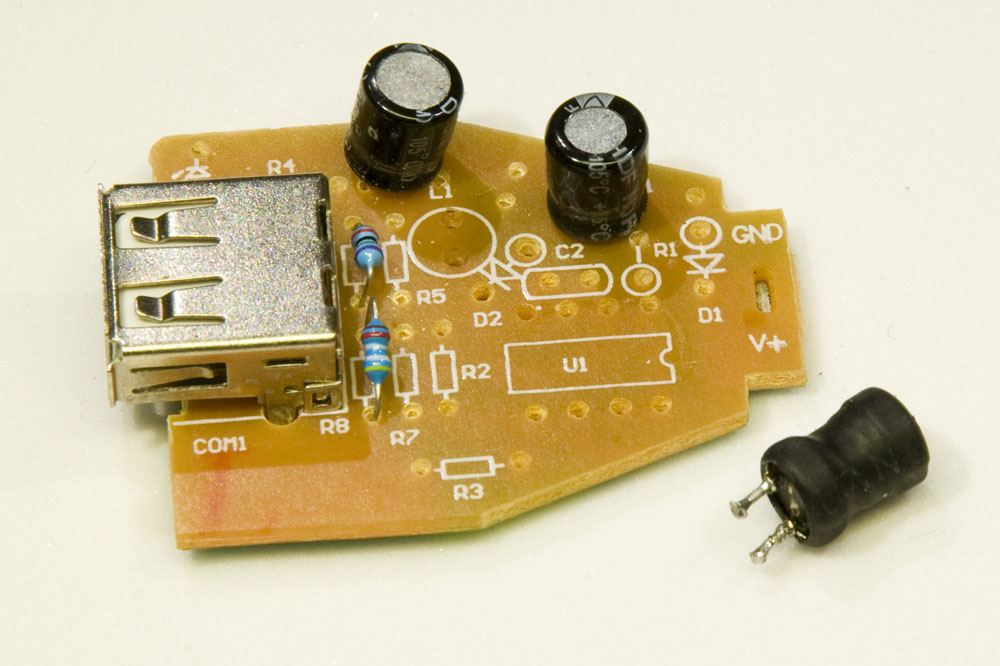
At first my intention was to make the modifications on the original PCB, but with a new and much larger inductor and especially a lot of reconnections required to accommodate the external PMOS transistor, I realized that it was actually more practical to desolder the MC34063A and a few other components and put the modified circuitry on a stripboard.
PCB-remains
The remains of the original DC/DC converter board with the useful components removed. Original inductor (L1) at lower right.

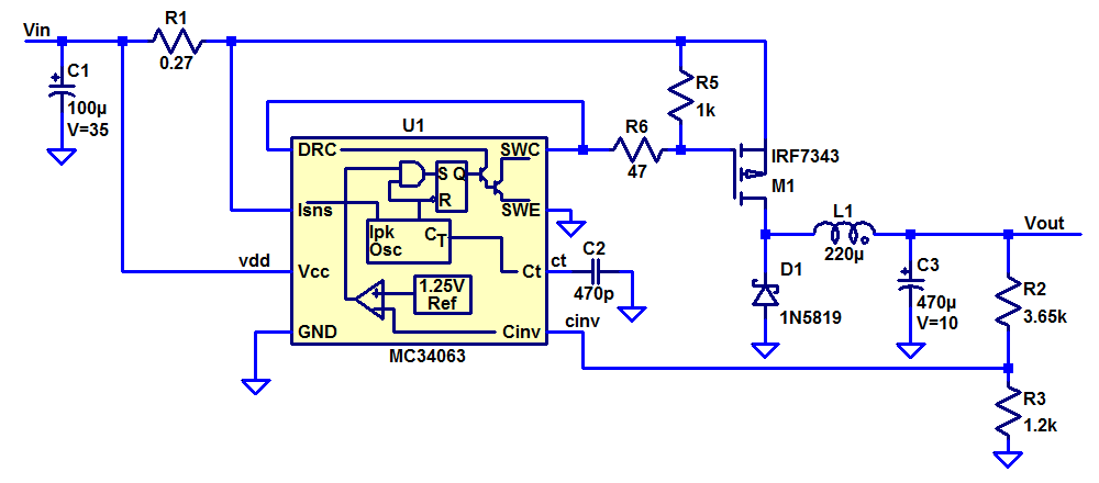
I bought a new inductor (220 µH, 1.9 A) and used a PMOS power transistor I had at hand. The PMOS was actually half of an NMOS/PMOS pair in an SO8 package (an IRF7343) so I had to solder wires to some pins to adapt it to the stripboard.

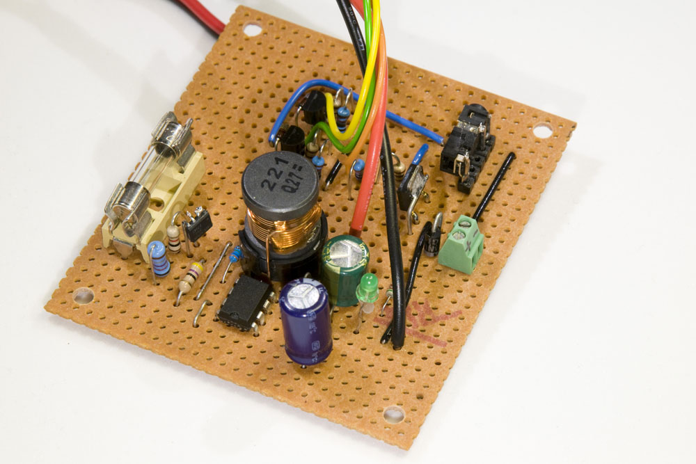
I did also replace the electrolytic capacitors at the input and output (47 µF and 330 µF) with ones having higher capacitance (100 µF and 470 µF) and lower ESR. The resulting schematics and the physical board can be seen below.
Schematics of DC/DC converter
DC/DC converter built on stripboard

I measured the output voltage and efficiency to see if the new design was any better than the original one. It turns out that it was. Below are graphs illustrating this.
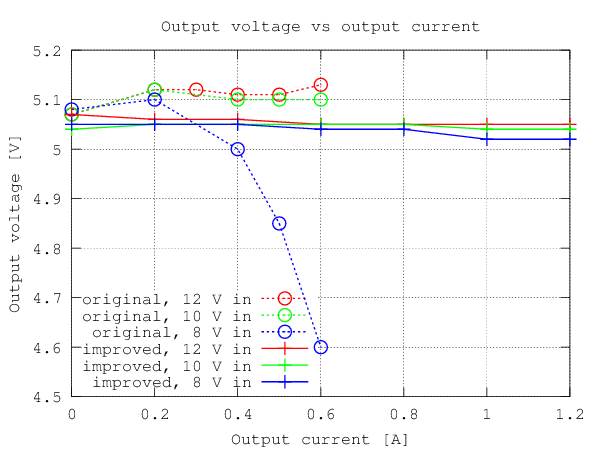

Output voltage plot
Output voltage vs output current for a few different input voltages. The new design works fine up to at least 1.2 A.
Efficiency plot
Efficiency vs output current for a few different input voltages for the original and new DC/DC converter designs. The efficiency of the new design is well over 80% for currents between 400 and 1000 mA, whereas the original design never reached 80% efficiency and was unable to supply more than 600 mA.

So the new design is a great step forward both in terms of output current capability and efficiency. In terms of size and cost of components it is far from optimal, but those were not important design parameters. If a smaller and more cost effective design is desired, a more modern switcher with higher switching frequency and a custom board layout could be used.

Motor drive

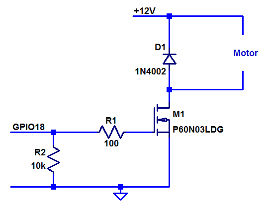
The motor used is a simple 12 V DC-motor with a gearbox bringing the speed down to 15 RPM. To move the dolly a small distance, the motor is simply turned on for a short period of time (150 ms was used by David Hunt, the man behind the Lapse Pi). For the Raspberry Pi to be able to control the DC motor, we need a transistor that is able to handle the current of the motor. David Hunt used an NPN, but I decided to use an NMOS from the junk bin. Many different transistor models could be used. The main requirements are a low enough threshold voltage for the limited I/O voltages of the Raspberry Pi to turn it on and sufficient drain current capability. I happened to have an old P60N03LDG and this one works fine, although its 60 A maximum current is extreme overkill. The threshold voltage is 2.5 V maximum and the R Pi should have no trouble supplying a voltage higher than this on its 3.3 V I/O lines.

I added a series gate resistor to limit the gate charge/discharge current and a pull-down resistor to make sure the transistor is off if not actively driven. A flywheel diode is also mandatory to take care of the current from the collapsing magnetic field when the motor is switched off. A schematic is shown below.
Schematics of motor drive transistor
Schematics of motor drive (a much wimpier transistor can be used).

Camera shutter control

For the shutter release, David Hunt suggests a single transistor that controls the shutter via a remote release cable. That might work for Canon cameras, but here we are dealing with Nikon and in my experience (based on a D300), you first have to ground the focus wire, wait for perhaps 300 ms and then ground the shutter wire. Therefore I used two GPIO pins on the Raspberry Pi, each controlling one signal from the camera. I used the same kind of 2.5 mm stereo jack that fits my existing remote release cable and for transistors I used BS108 NMOS transistors with a threshold voltage of at most 1.5 V. The schematics is shown below.
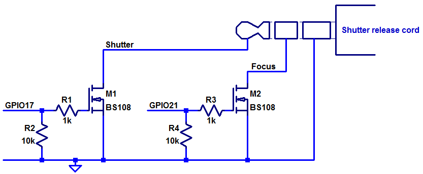
Schematics of focus and shutter control.
Schematics of focus and shutter control

Raspberry Pi connector

I use the GPIO connector of the Raspberry Pi to both connect to the GPIO signals and to power the board. This eliminates the need for two separate connectors at the R Pi end of the cable. A minor disadvantage of not powering it through the micro USB connector is that the fuse on the R Pi is out of the circuit. A secondary side fuse could be added to the DC/DC converter board, but I think I will stick with just having a fuse on the primary side of the DC/DC.

Below is a photo of the whole thing, including the GPIO connector. The motor connects to the small green screw terminal (partly hidden on top center of the board) and the shutter release cable connects to the black stereo jack at the top left. The green power indicator LED can be removed to save some precious battery power.
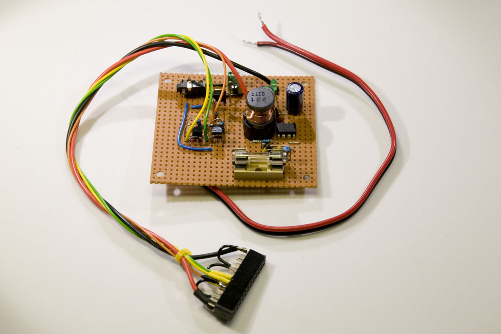
The finished board with all the electronics.


Review of New Arduino Nano from Banggood

As I wrote in a previous blog post, I had a bad experience when ordering some Arduino Nanos (SKU066316) from Banggood.com. The products turned out not to be working due to faulty and possibly counterfeit FT232RL chips (USB to serial port converters).

“Thea” from Banggood commented on the post and as a result of my criticism, Banggood claims to have changed their supplier. Almost a month ago Thea offered to send me one of their new Nanos for me to review and today I received it. The parcel was stamped 2013.12.12.20 (not sure what the trailing “.20” means) which probably indicates it was sent on the 12th of December, just after Banggood said they were about to ship it. So the delay is probably just the time it took for the mail to get here.

This blog post is a review of what I received. A short summary is that the board I received performs slightly better than the old boards, but that there still seems to be major problems and possibly still a counterfeit FT232RL chip that is at the root of the problems.

Appearance

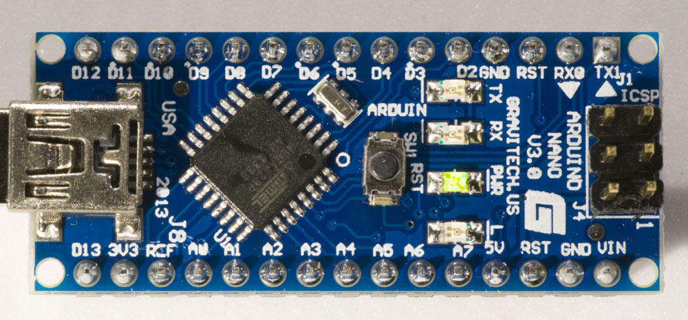
The new Arduino Nano I got looks a little different from the old ones. It has the following text printed on it:

ARDUINO
  NANO
  V3.0
GRAVITECH.US
ARDUIN
USA 2013

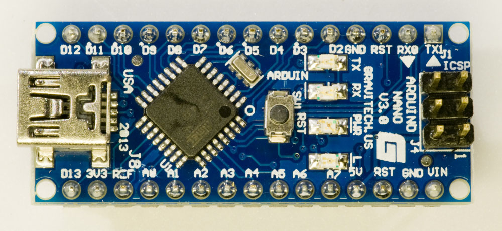
This is what it looks like:

Top side of Arduino Nano
Top side of Arduino Nano, claiming that it is made by Gravitech
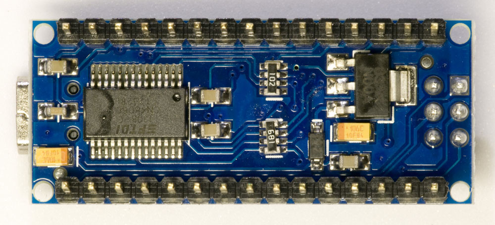
Bottom side of Arduino Nano

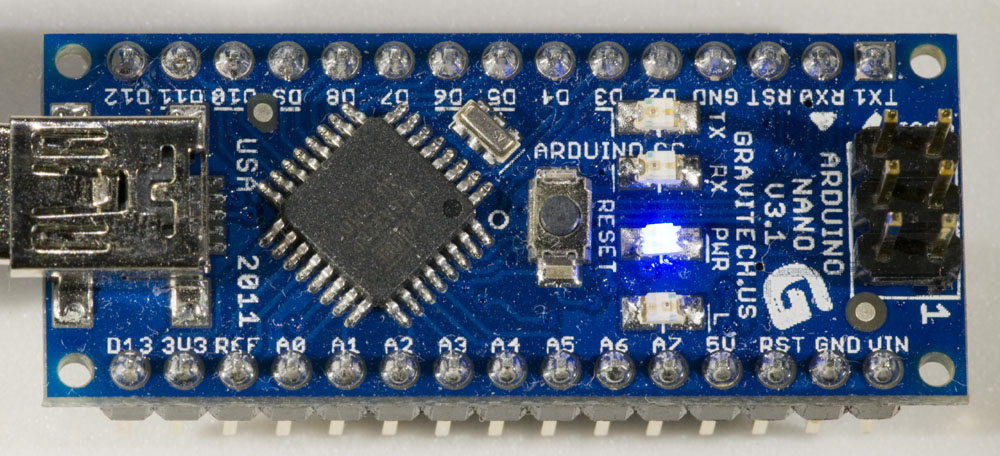
Gravitech is the company that designed and originally built the Nano. Since long ago, I have a Nano made by them (probably bought through Digikey) and on it is printed V3.1 and “USA 2011”. It seems a bit odd that they would be making V3.0 in 2013 when they were already making V3.1 in 2011, but I guess that it is possible that they maintain two versions for some reason.

Power LED color

On Gravitechs web site, they say that the Nano V3.0 has a blue power LED. This is true for the old Arduino Nano that I have, but not for the new one I received from Banggood. Below are photos of both the new and old board when powered up, showing the green LED on the board from Banggood and the blue LED on the old board.

Green power LED
Top side of Arduino Nano from Banggood with green power LED.
Blue power LED
Top side of old Arduino Nano bought on Digikey with blue power LED.

Well, the power LED being green instead of blue is not a problem for me. The fact that the text says “ARDUIN” on the Banggood board and “ARDUINO.CC” on the Digikey board is curious. Is it likely that Gravitech has introduced that error after getting it right a few years ago? A picture at the bottom of the Gravitech page for Arduino Nano does show correct silkscreen print on a V3.0 board from 2009…

Problems when connecting the Arduino to the computer

I connected the board to my computer (running Windows 7, 64-bit) via a USB cable. At first it did not appear as a USB serial port, but unplugging and reconnecting it made it show up as COM16. I tried to upload a sketch to it and that worked. So far so good.

Then the problems began. I tested to unplug and reconnect the board several times and it turns out that it very often does not work as it should. A few different things happened at different times:

  • The USB serial port shows up as it should in the Device Manager.
  • An unrecognized USB device shows up in the Device Manager.
  • A pop-up message says the device failed to start.
  • The device is completely unrecognized.
  • The computer crashes with a blue screen of death (BSOD).

Here is an account of a series of tries:

  1. Not recognized.
  2. Works fine.
  3. Not recognized.
  4. Computer crash (BSOD).
  5. Works fine, but with a new COM port number (I think it should always be the same).
  6. Works fine.
  7. Not recognized.
  8. BSOD
  9. Works fine.
  10. Not recognized.
  11. Cannot start.
  12. Not working, but shows up with a yellow question mark in Device Manager. Inactivating and then activating it got it working.
  13. As above, but inactivating and then activating did not help.
  14. Unknown device.
  15. Unknown device.
  16. Unknown device.
  17. USB serial converter could not start. Inactivating and then activating did not help.

Not exactly a stellar performance and clearly unacceptable, especially the BSODs.

As a reference I tried to plug and unplug both the old V3.1 Nano from Gravitech/Digikey and one of the Nanos I previously bought from Banggood and on which I replaced the FT232RL chip to get them working. Both of these units worked fine every time for at least 10 tries. The only exception is that a few times the computer did not recognize the unplugging of the Nano. I think that happened when the unplugging occurred rather quickly after plugging it in. But there were no problems with unrecognized devices or computer crashes.

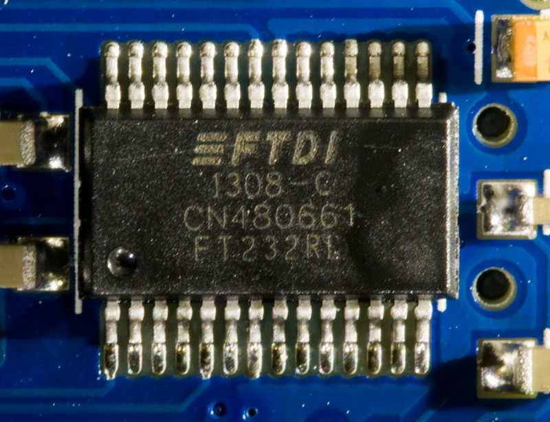
The FT232RL chip on the new Nano from Banggood has text that is laser marked (not printed) like the previous Nanos I have received from Bangood, but unlike all the other (working) FT232RL chips I have seen.

FT232RL
Close-up of the FT232RL USB to serial converter on the new Nano from Banggood.

So in while it was great of Banggood to send me a new unit to try, there still seems to be major problems with the Arduino Nanos from Banggood and my guess is that the FT232RL USB to serial converter is still the main problem. Perhaps it is (still?) counterfeit. It would be interesting to use a USB analyzer to compare the traffic between the (old) working units I have got and the intermittent one I reviewed here, but I currently do not have access to such a tool.

I also doubt that these Nanos are genuinely from Gravitech. The price seems way too low compared to what they are selling them for on their own web site, and the color of the power LED as well as the appearance of the silkscreen print on the board (missing letters, V3.0 still produced in 2013) casts doubts on the origin.

Multimeter repair

This is a story about troubleshooting and repairing a multimeter.   A technique on how to locate a short is described.

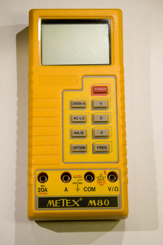
So, I was working on a project in the lab and needed to measure both voltage and current simultaneously, so I brought out an extra digital multimeter (DMM) I had on a shelf, a Metex M80. Unfortunately, nothing happened when I pushed the power button. Well, it had been unused for probably over a year, so maybe the battery was shot. I checked the 9 V battery and it measured 7.5 V or so. That should be enough to power the multimeter. Strange.

Metex M80
A dead Metex M80 multimeter.

I then checked the battery voltage while connected to the  DMM and now it was 0 V. Even stranger. Had the internal resistance of the battery become so large that the tiny current of the multimeter brought the voltage down to zero? That seemed unlikely, but I tried with a brand new battery and still got 0 V while trying to power the DMM. Not good. The instrument seemed to be shorted, and sure enough, the resistance across the DMM battery connector was 0 Ω while the power button was switched on.

Time for more serious troubleshooting.

I took the instrument apart and found a 2-layer PCB inside. My standard technique for finding where the short is between two conductors on a PCB is to use a lab power supply to inject a current (a few hundred mA typically, with voltage limited to 0.5 V or less to prevent damage if the short suddenly goes away) and measure voltage drop along the tracks. This is effectively four-terminal sensing, or Kelvin sensing where the test current is applied through two leads and the voltage drop is measured using separate leads; unlike how a common two-terminal ohm-meter works.

The current obviously flows from the lab power supply, through some tracks on the PCB, via the short, through some other tracks on the PCB and back to the supply. Wherever current is flowing through a finite resistance, there is a voltage drop (Ohm’s law) and although the copper tracks are pretty good conductors, a current of a hundred mA or more  will typically cause a voltage drop of at least a few mV, which can be easily measured.

So, by measuring the voltage drop across the tracks, it is possible to figure out where the current is flowing and thus where the short is located. If you put one probe on the point were a wire from the lab supply enters the board and you measure the voltage drop to various points along a track further and further away from the reference point, the voltage drop will be gradually higher and higher as long as the current is flowing in the track you are following. If the track branches (or if there is a component pin connected to it) and the voltage stays the same beyond the fork, you can conclude that the current is flowing in the other branch. This is perfect for figuring out where the short is located.

(As a side note, the same technique also works for boards with power and ground planes, although you might need to use more current and/or a more sensitive voltmeter due to the very low resistance of the planes. I have on a number of occasions located shorts between power and ground planes on multi-layer PCBs to with in a few mm.)

Below is a series of pictures showing how I applied the method in this case.

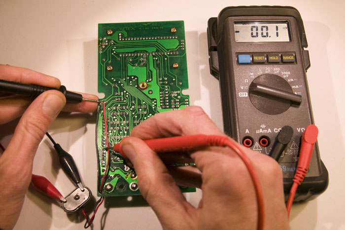
First I followed a track going south from the negative terminal. The voltmeter reads -0.1 mV (0 mV is well within the error bars here), so the conclusion is that this is not the way the current is flowing.

Measuring voltage drop
Measuring the voltage drop across a PCB track. No current seems to be flowing this way.

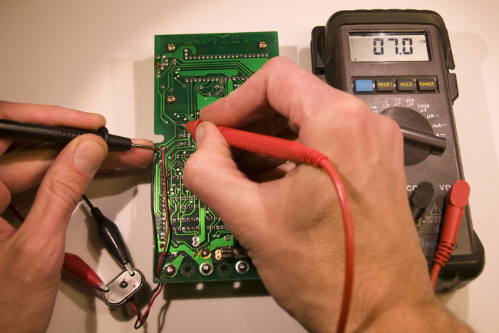
Then I followed the track north to the first fork, which happened to be a component pin. Here we can see a significant voltage drop of 7.0 mV, so current seems to be flowing in this track.

Measuring voltage drop
Here we see a voltage drop of 7 mV, so current seems to be flowing in this track!

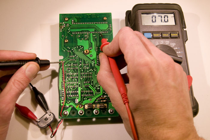
The track continues north and then turns east to another component pin, but the voltage is the same here, so the conclusion must be that the current came from the component pin in the previous measurement.

Measuring voltage drop
No further voltage drop despite a long piece of track since the last point. So the current came from the pin in the last measurement and not from up here.

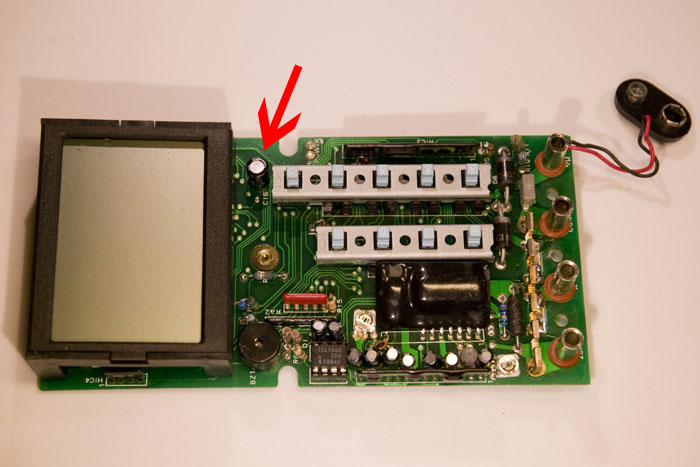
The pin with the current belongs to an electrolytic capacitor on the other side of the board. See photo below.

The suspect electrolytic capacitor,

Electrolytics are notorious for their degradation over time, so it is not too surprising that this component has failed. Especially since it turns out to be rated at +85 °C (good electrolytics are rated for at least 105 °C). It also has a voltage rating of  just 16 V, which does not provide a lot of margin as it is exposed to the voltage of a 9 V battery. It seems like the manufacturer of this DMM aimed for low cost rather than high reliability.

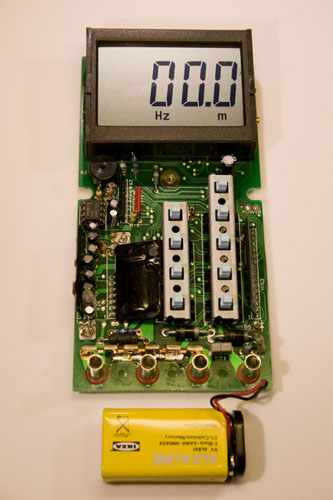
Replacing the capacitor was simple enough and, as expected, the removed component was internally shorted. After the replacement the short was gone and the multimeter worked!

Working multimeter
It’s alive!

So now I can go back from this detour to the project I was working on. Or rather, that will have to wait until tomorrow.

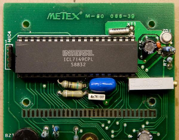
Update on 2014-02-23: Branko asked in the comments about what IC is in the M80 and it turns out it is an ICL7149CPL. Below is a photo of it.

The main IC of the M80, and ICL7149CPL.
The main IC of the M80, an ICL7149CPL