After the incandescent bulb of the bicycle light broke for the second time in a few weeks, I thought it was time to retire Edison’s invention and move into the 21st century by replacing it with an LED.
I had a cheap battery powered bike LED light laying around, but I wanted the LED to be powered by the hub dynamo and so I decided to convert it from battery power to dynamo power. The dynamo generates AC current at a voltage and current that depends both on the speed of the bike and on the load that is connected to it, so some circuitry had to be designed and built to suitably drive the LED.
The bike light contained a battery holder for four AAA batteries, a single power LED and a small circuit board containing a glob-top chip, a decoupling capacitor, a small external MOSFET and a connection to a button that could put the LED in one of three modes: off, on and flashing. Text printed on the light said “3W”, but I doubt the LED can actually handle that much power and I also doubt the four small batteries could deliver the close-to-one-amp of current required for 3 W. 300 mA and thus approximately 1 W seemed more reasonable. As a hub dynamo can easily generate more than 300 mA and I wanted to get the full brightness at a reasonably low speed while still not overloading the LED at higher speeds, some form of constant current source was required.
If I had wanted to spend lots of time and development effort on building the perfect dynamo-driven bike LED light, I would probably have opted for a schottky bridge rectifier followed by an elaborate switch-mode converter driving one or more big LEDs, preferably with a control scheme that tries to maximize the power put into the LEDs at lower speeds, while keeping the power constant at higher speeds.
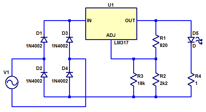
My priorities were however somewhat different with this project. I wanted a quick solution that I could finish in a few hours using components I had available at home. The solution I opted for was to build a bridge rectifier using four 1N4002s and follow it by an LM317 adjustable voltage regulator that drives the LED in series with a 1 ohm power resistor; see schematic below. By setting the output voltage of the LM317 to a suitable value, the 1-ohm resistor limits the current through the LED to the desired 300 mA.
Schematic for constant current bike LED light.
I first measured the LED voltage at 300 mA of current and selected feedback resistors to the LM317 to get a little more than 0.3 V above that value (to account for the voltage drop across the current limiting resistor). That gave me the values for R1 and R2. Then I built the circuit on perf board, but without R3. After that I connected the LED (D5 in the schematic) and tested it while powered from a bench supply. I added R3 as required to reduce the current to 300 mA. Depending on what LED you have and how much current you want to supply it with, you need to adjust the voltage divider R1-R2-R3 accordingly.
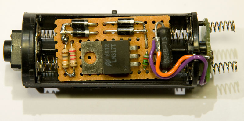
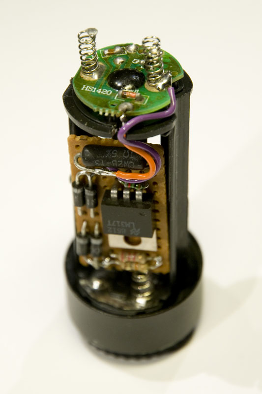
The finished circuit board is shown below while fitted in the battery compartment of the original bike light. The LM317 does not get a lot of cooling, so maybe it will be get quite hot if pedalling fast. If that turns out to be the case, I will have to figure out a way to thermally connect it to the housing.
Top view of the electronics fitted in the battery compartmentSide view of the electronics as well as the original circuit board that is left in place.
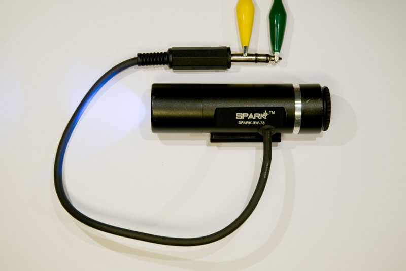
I drilled a hole through the housing and fitted it with a grommet suitable for the cable I intended to use to connect the light to the dynamo. I used a 6.35 mm stereo plug and put a corresponding jack on the bike so that the light could be unplugged and removed. Hopefully these connectors are robust enough to work reliably outdoors for a few years. We will see. The photo below shows the finished light.
Test of the bike light using a bench supply hooked up to the 6.35 mm plug.
A quick test drive demonstrated that the contraption worked as intended. The light flickers when the bike rolls very slowly, but for any reasonable biking speed, the light is stable. Maybe I will build a more powerful bike light in the future, but for now this will do.
I just bought a new laptop and it came with Windows 8.0. I had very low expectations based on what I had heard about 8.0. Windows 7 on the other hand I quite like, but that was not available as an option as most laptops today seem to come bundled with Win 8.
I have not yet gotten used to the new user interface (a main issue is the missing Start Menu), but I also ran into another nuisance when after installing all the normal Windows updates I upgraded to Windows 8.1. When the laptop first ran its set-up routines for Windows 8.0 there was an option to sign in using a Microsoft account, but there was also an option to just create a local account and for me the latter was the preferred method.
Instead of filling out all sorts of information about myself for the account, I clicked on a text at the bottom of the screen saying something like Continue with existing account (this might not be the exact wording).
This allowed me to continue with the set-up without creating an MS account. The blog post I linked to above lists two more ways of dodging Microsoft’s attempt to snare you.
I think it is very weasely of Microsoft to hide the fact that you can get around creating an account.
So let’s talk some electronics on this blog for a change.
The other day I responded to a forum post about decoupling. Others had responded before me, but I felt that there were room for additional insights. Here is a translation into English of the question and a somewhat extended version of my reply.
Q: It is common to have a decoupling capacitor between power and ground to get a stable supply voltage. In the case of a micro controller the value is typically around 100 nF. My question is: Do I still need the capacitor even at low frequencies (~8 MHz) and when the supply current is rather small, like a few mA at 3 V?
A: The subject of supply decoupling is far more complicated than what has previously been indicated in this discussion thread. But it is not magic.
You might be able to make it work without the capacitor if the circumstances are right and you can most certainly make it fail despite the capacitor if the circumstances are unfavourable.
I do not have the time to write anything remotely complete here and now (others like István Novák, http://www.electrical-integrity.com/ have written thick books about it), but I can try to describe some of the most relevant points for your case.
One good way of thinking about this subject is to realize that the goal is to make sure the impedance of the supply rail (or the Power Distribution Network, PDN, as it is often referred to in the literature) is low enough for all frequencies to prevent too high amplitudes of noise to appear. This observation is more or less trivial, but it is still a good starting point.
So, what impedance do you need and what will you get? My guess is that you have at most two copper layers on your PCB. This is a bad start, but it is quite possible to make slow processors work on such a board anyway. Ideally, you would want to have nice power and ground planes in the PCB with just a thin dielectric layer between them (preferably 0.1 mm or even less) to get a large (well, everything is relative) plane capacitance and a small inductance. This plane capacitance can typically be up to a few nF (a pair of 1 dm^2 planes separated by 0.1 mm of FR4 has a capacitance of 3-4 nF) which probably does not sound too impressive, but it has a very low inductance if the planes are solid and closely spaced and the planes are therefore good at keeping the impedance low at frequencies of maybe 100 MHz and up to a GHz or so. Above a GHz, the inductance of vias and packages makes the planes less relevant and decoupling inside chip packages and on the chips themselves are the only effective decoupling.
If you connect a surface mount decoupling capacitor to the planes and use a good layout with closely spaced vias you will get a parasitic inductance of approximately 1 nH. I have done some research on the inductance of various decoupling layouts and the results can be found here: https://axotron.se/index.php?page=28. The inductance depends not on the capacitance value, but only on the layout and the geometry of the capacitor package, so 1 pF in a 0603 package has the same inductance as 1 µF in the same package.
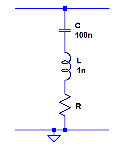
The parasitic inductance appears in series with the capacitor and forms a resonant circuit (there is also some small series resistance, but we will ignore that for now). See picture below.
Equivalent circuit for a 100 nF decoupling capacitor.
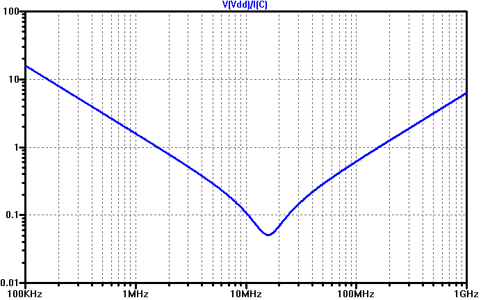
1 nH together with 100 nF results in a resonance frequency of 16 MHz. At this frequency the capacitor is maximally efficient since it has its lowest possible impedance. For frequencies below the resonant frequency, the impedance gradually increases (the capacitance dominates and its impedance increases at lower frequencies) and the same happens above it (the inductance dominates and its impedance increases at higher frequencies). The impedance vs. frequency is plotted below.
Impedance of a 100 nF, 1 nH capacitor vs. frequency.
The fact that the capacitor behaves pretty much like an inductor a bit above the resonant frequency does not mean that it is useless at those frequencies. The important thing is that the impedance is kept low enough. The impedance is indeed the same at a tenth of the resonant frequency (where the capacitance dominates) as it is ten times above (where the inductance dominates). So if you are happy with the capacitor impedance at 1.6 MHz (where it is roughly 1 Ω) you might be equally satisfied at 160 MHz (where it has reached 1 Ω once again).
Above 100-200 MHz or so, the planes typically have lower impedance than the decoupling capacitors and if you need low impedance in this range you really need a PCB with properly designed planes.
If you do not have the luxury of power and ground planes, things get worse. The planes are not there to connect the capacitors to the pins of the chip via a negligible inductance and you need to resort to using tracks to distribute the power. A rule of thumb is that a 1 mm long track has an inductance of approximately 0.5 nH (1 nH would be easier to remember and more conservative, but seems to be less accurate for typical PCB tracks). Maybe you are lucky and are using a chip that has power and ground pins next to each other so that you can put a capacitor right at this pin pair to get a decent low-inductance decoupling solution. This might actually work up to a few hundred MHz and if you are lucky again this covers the needs of the chip.
But let’s assume you put a single 100 nF capacitor at the voltage regulator and that it is 10 cm away from the chip. This gives 20 cm of tracks (the inductance in the ground tracks counts as much as the inductance in the power tracks if they have similar geometry) and results in an inductance on the order of 100 nH. This clearly dominates over the inductance of the surface mount capacitor and at 8 MHz (the assumed clock frequency of the processor), this yields an impedance of 5 Ω. If the processor consumes 10 mA at the clock frequency, the ripple is 50 mV, which probably will not cause any trouble for a 3 V digital circuit.
However, the supply current is unlikely to be a sinusoid at the clock frequency. Rather there will be a current spike once per clock cycle and if we assume that the amplitude is 20 mA and that the rise time is 1 ns, we have a time rate of change di/dt of 20 MA/s. This causes a voltage drop over the supply inductance of L*di/dt = 2 V. A ripple of 2 V on a supply of 3 V is not good and is almost guaranteed to cause malfunction. The numbers will be different in each specific case, but the numbers used here are quite realistic and the calculation shows that a few cm of tracks between the decoupling and the chip might be disastrous. If you instead have a board with good planes, the inductance of the planes is so tiny compared to the inductance of the capacitors, so it does not matter much if there are several cm between the decoupling capacitors and the chip.
It is worth pointing out that the above analysis of the current spikes did not assume any particular clock frequency. So it does not matter if they occur once per minute or a hundred million times per second. The resulting noise amplitude will be the same. So the possibly unexpected conclusion is that the switching time (and amplitude) is far more important when it comes to decoupling than the actual clock frequency.
The rise time of outputs is sometimes specified in the datasheets, but then often as maximum values and the interesting thing for decoupling purposes is the minimum rise time. The AC characteristics of the current consumption of the processor itself is rarely, if ever, specified.
In summary, you probably need to use proper decoupling techniques even if the processor is clocked at a relatively low frequency.
There are also more complicated aspects that one might need to consider, but I refrain from going into those in detail here. E.g. if you have several capacitors in parallel, and especially if they have different capacitance and/or inductance, there will be parallel resonances where the impedance peaks, which could cause serious problems. If you have planes, there will also be such a resonance between the capacitance of the planes and the inductance of the decoupling capacitors.
One thing that you should (almost) never do is to put a ferrite or other inductor in series with the supply of a digital circuit. Doing so would add lots of inductance to the supply and thus cause the circuit to much more easily generate a huge amount of ripple on its own supply.