This is a story about troubleshooting and repairing a multimeter. A technique on how to locate a short is described.
So, I was working on a project in the lab and needed to measure both voltage and current simultaneously, so I brought out an extra digital multimeter (DMM) I had on a shelf, a Metex M80. Unfortunately, nothing happened when I pushed the power button. Well, it had been unused for probably over a year, so maybe the battery was shot. I checked the 9 V battery and it measured 7.5 V or so. That should be enough to power the multimeter. Strange.
I then checked the battery voltage while connected to the DMM and now it was 0 V. Even stranger. Had the internal resistance of the battery become so large that the tiny current of the multimeter brought the voltage down to zero? That seemed unlikely, but I tried with a brand new battery and still got 0 V while trying to power the DMM. Not good. The instrument seemed to be shorted, and sure enough, the resistance across the DMM battery connector was 0 Ω while the power button was switched on.
Time for more serious troubleshooting.
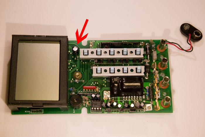
I took the instrument apart and found a 2-layer PCB inside. My standard technique for finding where the short is between two conductors on a PCB is to use a lab power supply to inject a current (a few hundred mA typically, with voltage limited to 0.5 V or less to prevent damage if the short suddenly goes away) and measure voltage drop along the tracks. This is effectively four-terminal sensing, or Kelvin sensing where the test current is applied through two leads and the voltage drop is measured using separate leads; unlike how a common two-terminal ohm-meter works.
The current obviously flows from the lab power supply, through some tracks on the PCB, via the short, through some other tracks on the PCB and back to the supply. Wherever current is flowing through a finite resistance, there is a voltage drop (Ohm’s law) and although the copper tracks are pretty good conductors, a current of a hundred mA or more will typically cause a voltage drop of at least a few mV, which can be easily measured.
So, by measuring the voltage drop across the tracks, it is possible to figure out where the current is flowing and thus where the short is located. If you put one probe on the point were a wire from the lab supply enters the board and you measure the voltage drop to various points along a track further and further away from the reference point, the voltage drop will be gradually higher and higher as long as the current is flowing in the track you are following. If the track branches (or if there is a component pin connected to it) and the voltage stays the same beyond the fork, you can conclude that the current is flowing in the other branch. This is perfect for figuring out where the short is located.
(As a side note, the same technique also works for boards with power and ground planes, although you might need to use more current and/or a more sensitive voltmeter due to the very low resistance of the planes. I have on a number of occasions located shorts between power and ground planes on multi-layer PCBs to with in a few mm.)
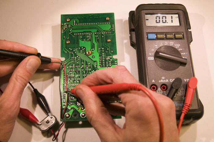
Below is a series of pictures showing how I applied the method in this case.
First I followed a track going south from the negative terminal. The voltmeter reads -0.1 mV (0 mV is well within the error bars here), so the conclusion is that this is not the way the current is flowing.
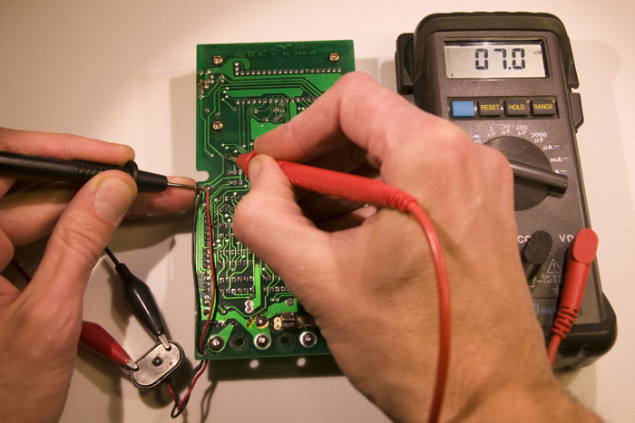
Then I followed the track north to the first fork, which happened to be a component pin. Here we can see a significant voltage drop of 7.0 mV, so current seems to be flowing in this track.
The track continues north and then turns east to another component pin, but the voltage is the same here, so the conclusion must be that the current came from the component pin in the previous measurement.
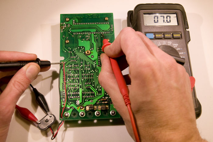
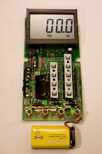
The pin with the current belongs to an electrolytic capacitor on the other side of the board. See photo below.
Electrolytics are notorious for their degradation over time, so it is not too surprising that this component has failed. Especially since it turns out to be rated at +85 °C (good electrolytics are rated for at least 105 °C). It also has a voltage rating of just 16 V, which does not provide a lot of margin as it is exposed to the voltage of a 9 V battery. It seems like the manufacturer of this DMM aimed for low cost rather than high reliability.
Replacing the capacitor was simple enough and, as expected, the removed component was internally shorted. After the replacement the short was gone and the multimeter worked!
So now I can go back from this detour to the project I was working on. Or rather, that will have to wait until tomorrow.
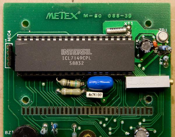
Update on 2014-02-23: Branko asked in the comments about what IC is in the M80 and it turns out it is an ICL7149CPL. Below is a photo of it.
Hi.
I need manual METEX m80 , what are the multimeter measurement ranges. I, U, R and F , could you write me ? Please .
Than you.
Full scales are:
DCV: 0.4, 4, 40 and 400 V (10 Mohm input impedance)
ACV: 400, 700 V
DCA: 4, 40, 400 mA, 2, 20 A
ACA: 4, 40, 400 mA, 2, 20 A
R: 4, 40, 400, 4000 kohm
F: 4, 40 kHz
Do you want any more detailed information than that? Like the accuracy for any specific range? I am not eager to scan or copy the whole manual (my copy is in German BTW), but if there is something specific you want to know I can perhaps check that for you.
that’s good, thank you very much. :)
Can someone tell me which integral circuit ICL7???CPL is using Digital Multimeter Metex M80.. Thanks!
Hi Branko,
It is an ICL7149CPL.
/Per
Thanks a lot!! You have a drink from me when you come to Serbia !! :)
:-) I added a picture of it at the end of the blog post.
Dear Sir, I am thankfull to you for your nice and clear explanation of the DMM defect.
I have the same problem: a new and long unused DMM M80 with a hardly visible
display digits. I suppose your helpful explanation to put into my practice.
Possibly you to have the wire diagram of the device. It would be very kind of you
to let me get aquainted with it. Thanks.
Best regards Yu. Tomakh
Hi Yuriy,
I do not have the schematics, but I doubt it is necessary to troubleshoot your device. Check if it consumes a lot of current (100 mA or more). If so it might have the same problem as mine had, namely a broken electrolytic decoupling capacitor.
I guess barely visible digits might also be caused by bad contact between the main PCB and the display. You could try to take it apart and clean the contact surfaces using e.g. a cotton swab and some alcohol.
Good luck with the troubleshooting!
Per
Hi I have an Fieldpiece digital multimeter that is not coming on I replace the battery and it doesn’t show the numbers on the small screen the fuse are good I remove the battery put it back know is giving me a beep sound were ever I turn the range I was looking to see if I could find an skematic diagram to make it more easy for me can’t you help me with this matter I’m electronic technician what else can I check I will appreciate your help
Hello,
Got a Metex M80 found on a second hand market, no manual with it.
Somebody have any idea wher i can find it?
Thanks for effort.
I need value r1 its burnt
R1 on my unit is white-white-yellow-brown-green, so 9.94 kohms, 0.5%. Measured with a Fluke multimeter (still while soldered to the Metex), the resistance across it is 9.92 kohms, so it seems plausible that 9.94 kohms is correct.
Does it say in the manual how to put it in diode mode. Since the diode/continuity seems to share the same button. I’m having trouble getting the voltage drop reading when trying to find the correct setting.
Yes. Press Ohm, then AC L-ohm, then OPTION. The continuity and diode test is the same mode. It says in the manual that the number shown in the display is the voltage drop in millivolt, if you ignore the decimal point and the kohm-sign.
But it gives me false readings. I tested a 1N4004 and it said 8.09 meaning 809 mV. I simultaneously checked the drop over the diode during this measurement using another multimeter and it read 448 mV. So either the accuracy is extremely poor or my unit is broken. The other multimeter gave a reading of 538 mV when I used it in diode mode to test the same diode.