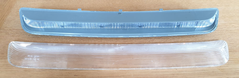
This article describes how I fixed a non-functional third brake light of a Toyota Avensis Wagon. This light is centrally located in the spoiler of the rear door and it is not obvious how to remove it.
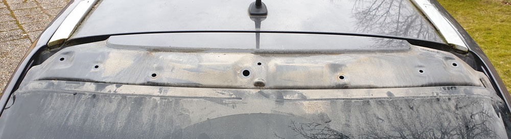
To get to the light, open the rear door and unsnap the trim in the red box in the photo below by carefully prying at the left and right edges.
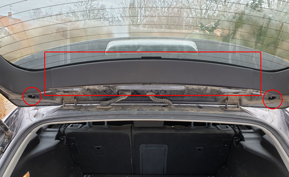
Remove the two rubber covers in the corners of the door, indicated by circles. They are already removed in the photo above.
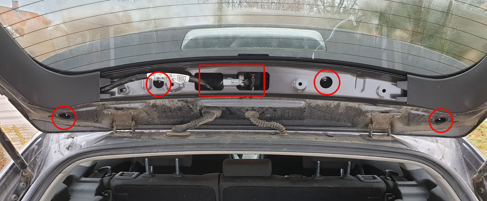
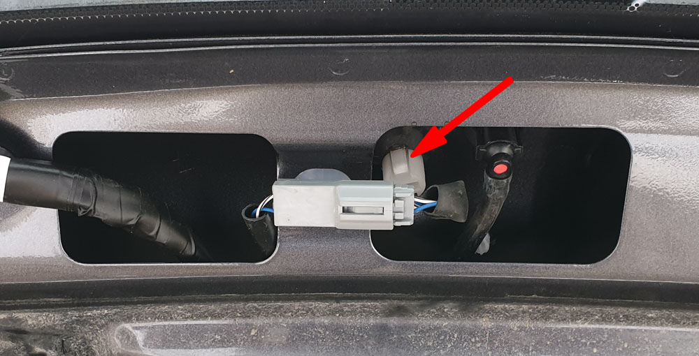
Unscrew the four nuts in the circled holes. Be careful not to drop the nuts inside the door. Unplug the connector in the red box by pressing down on the locking mechanism and pulling the halves apart.
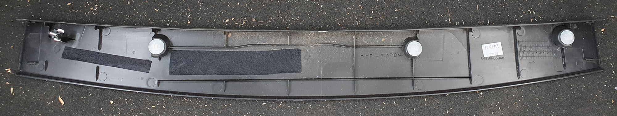
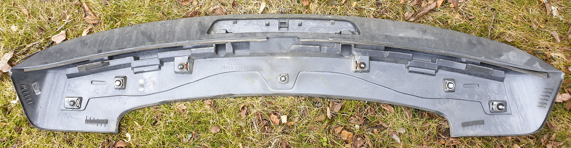
The spoiler is held in place by the four nuts that were just removed as well as with a few snap pins. Close the rear door and carefully pull the spoiler up so that the snap pins let go. Also be careful that the cable for the brake light does not get stuck in the hole when lifting off the spoiler.

Remove the two screws holding the brake light.
If you want to just buy a new lamp, this is as far as you need to go with the disassembly. The part number for the lamp is 81570-05110 and it seems to be available from https://www.amayama.com/ (no affiliation) or probably from your local Toyota dealer (at three times the price in my case). I managed to repair the lamp, so I did not have to buy a new one.
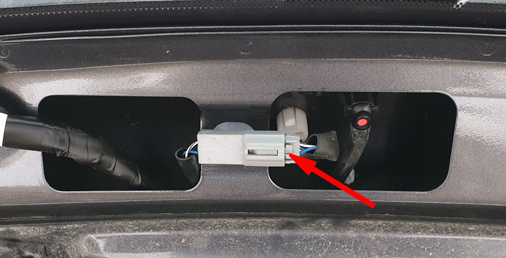
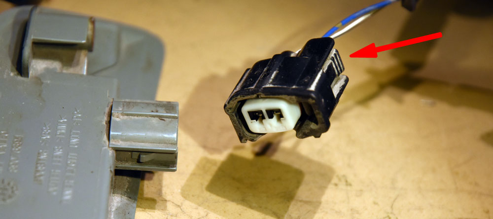
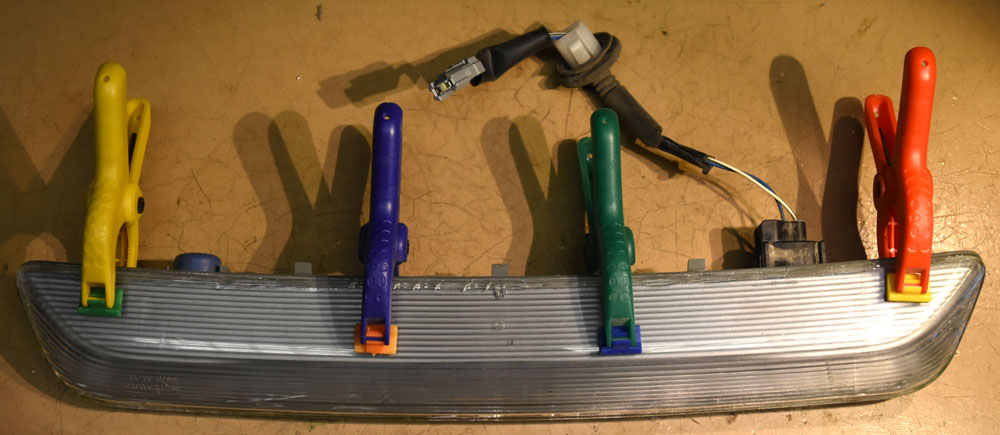
The cable can be removed from the light. It is secured in place by a locking mechanism, so the lever pointed to by the arrow needs to be pressed in to detach it.
Now the hard part begins. The light is not made to be taken apart. It seems to be glued or welded together. I managed to separate the outer lens from the base by first heating it all up to 90 degrees (do not go higher, or it will deform) and then using a knife to pry the pieces apart. I do not know if this generally works or if I was lucky. There is a significant risk that the outer lens cracks.
Another, perhaps safer, but less elegant way is to use a Dremel or similar with a cutting disk to cut the pieces apart. This is less likely to crack the brittle transparent plastics, but does of course leave a larger gap to fill with glue when the unit it to be reassembled.
(I had to resort to the Dremel method the second time I took it apart since I had then glued it together with super glue (CA) which did not otherwise give up its grip. See further below.)
The difficulties are not quite over yet. Inside the base part, there is an inner lens that spreads out the light and holds the PCB with the LEDs. This lens is held in place by a hidden claw on each side and it needs to be removed so that we can get to the PCB. The photo below points to the claws.
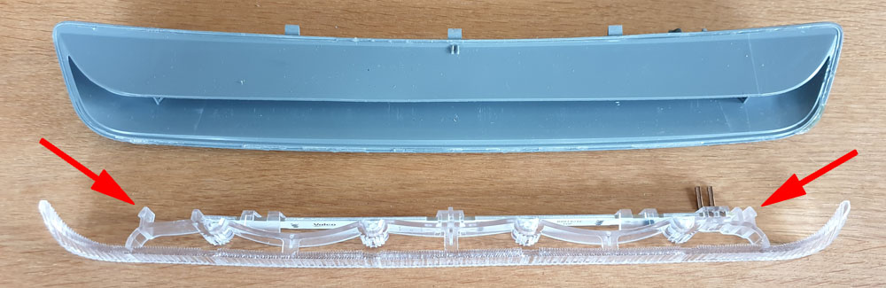
The way I managed to remove the lens was to put a screwdriver in the middle and bend the central part of the lens forward. It would probably have helped to simultaneously push inwards on the lens from the left and right, but I did not know retention mechanism at this point. For me, the front piece of the lens cracked in one place and then it was easy to remove. The crack did not matter since the lens was held together by the rear part, so it was still in one piece.
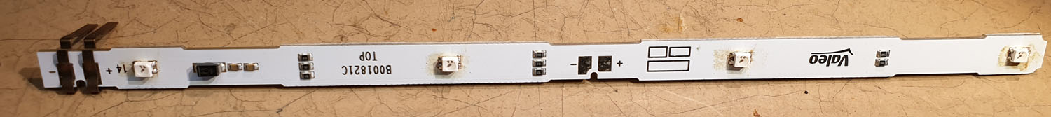
The PCB with the LEDs slides into the lens, see the rectangle below. It can easily be removed.
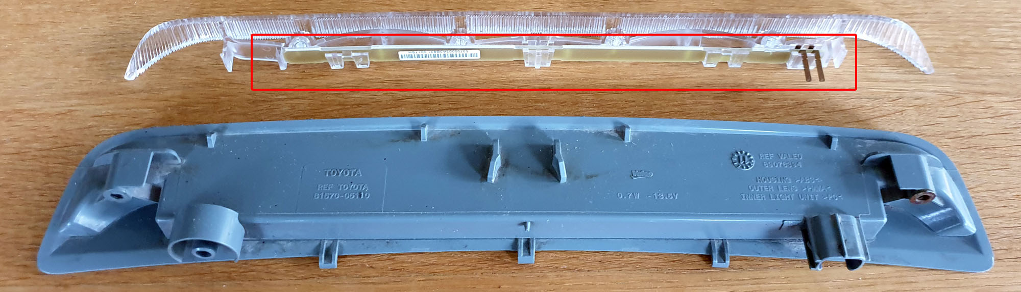
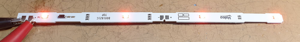
The PCB is covered with dense white solder mask, so the trace pattern is hard to see. However, the circuit seems to be essentially a series connection of four LEDs and some current limiting resistors.
I tried to power the circuit with 12 V from a current limited lab supply, but nothing happened, as expected. After some inspection, I noticed that one of the LEDs had a cracked solder joint.
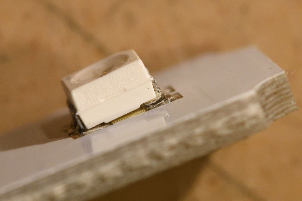
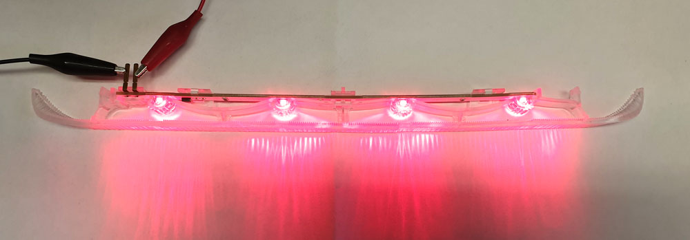
After fixing this, the light started working! Be careful not to use the wrong polarity when powering the light. The polarity is clearly marked on the board.
I put the PCB back, glued the outer lens to the base using CA glue (turned out to be a mistake later) and reassembled the parts to the car.
A few days later I discovered that the brake light did no longer work. :-(
So I had to disassemble the whole thing again and this time it was even harder to remove the outer lens from the base of the light since my CA glue did not want to let go. I tried to heat it up to 110 degrees C, but this slightly deformed the assembly, so that was a mistake. It also did not soften the CA glue enough to allow removal of the outer lens.
I had to resort to the Dremel method to separate the lens from the base.
I discovered that two of the LEDs were broken. I do not really understand what caused this failure, but I noticed the lenses of the LEDs were very soft. A wild speculation is that the fumes from the curing CA glue did mess with the LED lenses and caused the parts to fail.
I decided to replace all the LEDs. They come in a package called PLCC-4 and has the anode connected to three pins and the cathode to one (marked by a bevel). I found that LSE6SF-V2BA-1-1 from Osram seemed to be a good replacement, so I bought a few of these (from TME, but they are also available at Farnell and other distributors). It is of course important to get the rotation right when installing the new LEDs. The little bevel exists on both the old parts and the new, so carefully note where the bevel is and place the new LEDs with the same rotation.
One thing I noticed is that the inner lens that more or less grabs around the LEDs is rather tight and tries to push the LEDs towards the center of the board. Maybe this is what caused the original cracked solder joint. To make this less of a problem, I installed the two outer new LEDs a fraction of a mm closer to the center of the board, rather than centered on their footprints. This seems to cause less of an interference between the inner lens and the LEDs.
A quick test shows that the light is again in working condition.
Now there was a bigger gap to fill when gluing the parts together, so I used hot glue. First I pre-heated the parts to 90 degrees to give the glue a better chance to get a good grip and then I applied the glue and quickly put the pieces back together.
This time the repair seems to be more durable, even though it is a bit ugly if you look very closely due to the deformed plastics and hot glue. But it works and it should pass the yearly inspection.
Tusen tack för beskrivningen. Det gjorde min inledande process så mycket enklare.
Har 4 av de 5 leds döda på min PCB.
Supertack!
Köpte begagnad lampa från “den där internetsajten med alla bilskrotar” och monterade isär efter dina anvisningar. Och satte ihop. Och det funkar. Och jag kan besiktiga bilen utan att skämmas.
Fantastisk bra beskrivelse, samme diode var løsnet på mitt print. Loddet og fikset !
Tusen takk !
Paljon kiitos neuvoista. oli samanlailla irronnut. Sain juotettua ja toimii.
Tack, denna guiden gjorde det enkelt att byta mitt bromsljus. Bytte hela insatsen, för den som vill prova att även byta led har jag kvar den gamla som jag kan sälja för en billig peng.