One use for the CNC mill I wrote about in the previous post is to depanelize PCBs, i.e. to mill out individual printed circuit board from a larger panel.
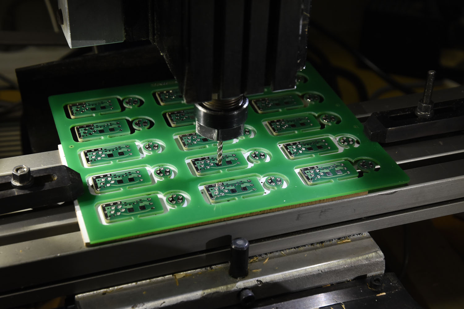
My first attempt att doing this was with a panel of PCBs that were already almost completely routed out from the panel. Only a small tab remained that held each board to the panel. I had designed the panel with “mouse bites” (a row of small holes) along the board edges towards the tabs, but due to an error on behalf of the PCB manufacturer, these holes were never drilled. (I did later receive a new set of panels with this error corrected, without extra cost.)
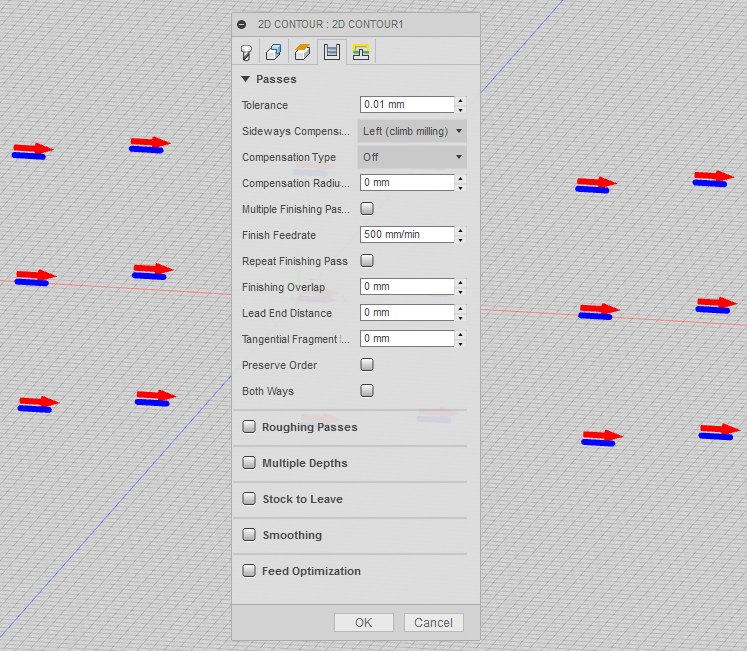
Based on the CAD files for the panel, I made a drawing in DraftSight with a center line for the mill through each tab. I imported the resulting DXF file into Fusion 360 (via the Upload feature) and created gcode using the 2D contour method with compensation set to Off to make the tool follow the center of the line. Using Fusion 360 for this is severely overkill, but it works.
I put the origin of the gcode in a place that was easy to locate on the board so that I could zero the coordinate system of the mill properly. I also took care to align the edge of the panel with the edge of the mill table. Since the panel was taller than the working area of the mill, I could not make a single program that would depanelize all boards. Instead I made a program that cut out three of the five rows and ran it twice with the panel appropriately moved on the table between the runs.
I did run into a couple of problems though:
Uploading the small DXF file to Fusion 360 took a long time (several minutes). I later realized that there is a menu alternative under the Insert menu that might have worked better.
Another and more serious issue is that Fusion 360 decided to silently interpret the DXF file as if the units was cm (who in their right mind draws in cm???). My drawing was of course in mm, so the resulting gcode instructed the CNC mill to move ten times longer than intended. I did not discover this until the mill started to move in unexpected ways that might have easily broken off the tool, had I not been quick enough to stop it and figure out what was going on. The Insert/Insert DXF function allows the user to select the unit, so this seems like a much better option to get DXF into Fusion than the Upload function. I will use that method in the future.
Once the mm/cm issue was resolved and new gcode was created I successfully depanelized the PCBs:
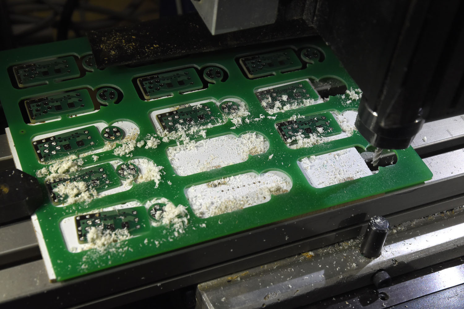
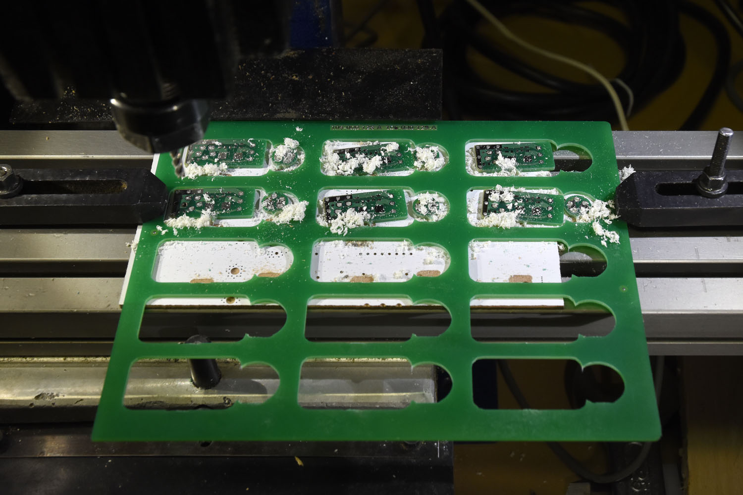
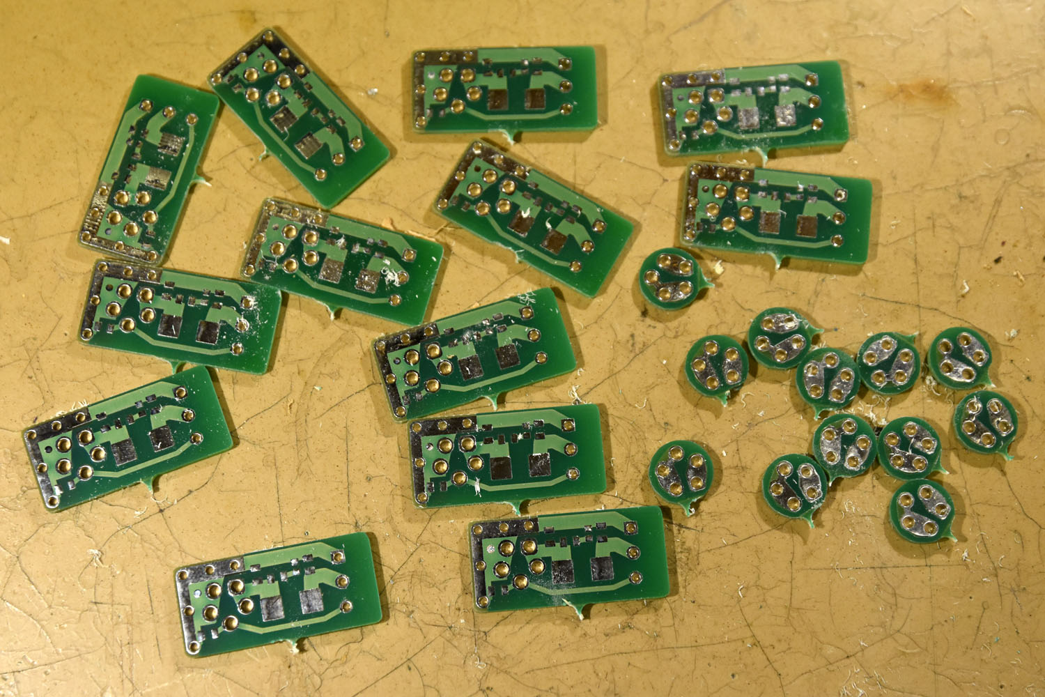
An artifact that is obvious on the individual PCBs is that a pointy remnant of each tab is still present. This is because the PCBs are only held in place by the tab, so when the tab is almost cut through, it bends and the board is pushed away so that the final part of it is not removed. The way to prevent this would be to somehow hold the PCBs in place independently of the tabs, but this is tricky, especially with the very small PCBs in this panel.
One thought on “Depanelizing PCBs with the CNC mill”