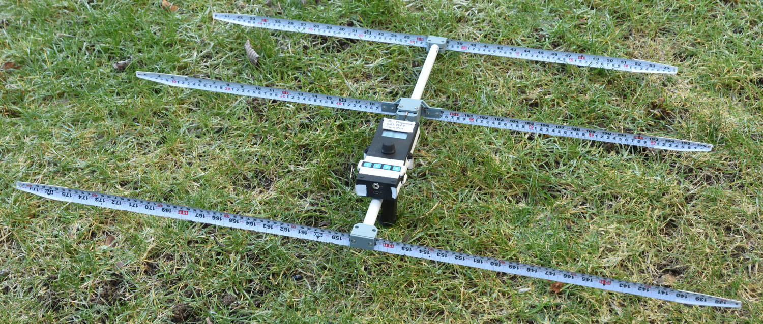
I have previously published two versions of a 3D-printed tape measure Yagi antenna design for “fox hunting” on the 2m band (144 MHz):
This article presents some slight improvements over the previous designs. The handle is less complicated and lighter and there is better protection for the elements from getting kinked. A drill guide for helping with drilling the holes in the elements is also included.

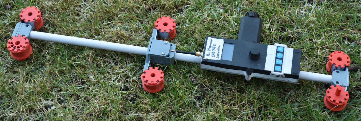
Like before, the tape measure elements can be rolled up on spools for storage and transportation:

The antenna/receiver can easily (with the help of a screwdriver) be further compacted for transportation:


Here is a link to a zip-file with the 3D models for printing:
Link to a zip-file with 3MF models of the parts:
New Features
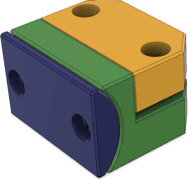
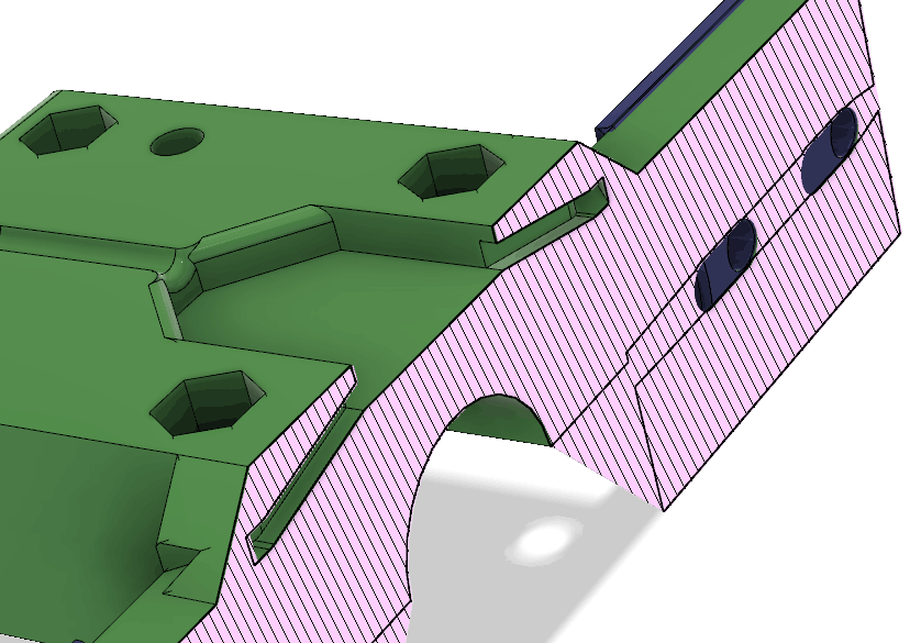
The director (front) element is now protected from sharp bends by a clamping piece (blue in the figure below) that sticks out a little to the sides:

The reflector (rear) element has a clamp that extends further than before (blue in the figure below) to avoid sharp bends:

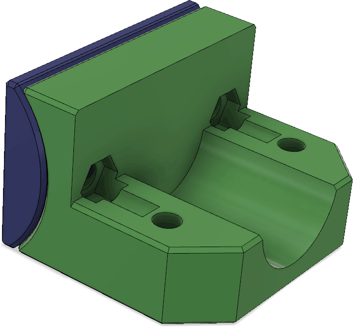
The driven elements are better protected from sharp bends by a piece that sticks out further than before (green in the figure below):

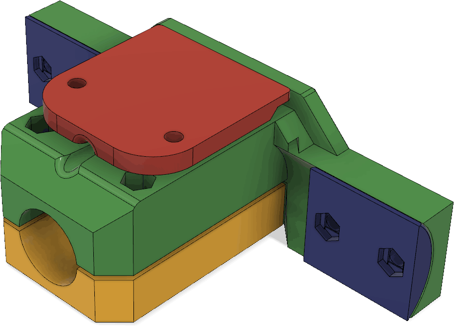
The handle is simpler. Now there are just two M3 screws that holds the clamp. No complicated pivoting clamp controlled by a long M4 screw through the handle. I have found this to work at least as well as the earlier version while being slightly lighter and easier to assemble.

It can be hard to drill the holes in the tape measure correctly. Both to get the holes in the correct positions and to get clean holes. To help with this, I designed a 3D-printed drill guide that is augmented with 5 mm thick steel plates:


There are five holes in the guide. The outer pair is for the front and rear elements. The inner pair is for the driven elements, while the center hole can be used when/if drilling holes at the tips of the elements for better traction when rolling them up on the spools.
The masking tape in the photo serves to adjust the amount of play between the pieces.
The steel plates have the dimensions 5x15x37 mm. Glue them in place in the recesses in the two pieces using epoxy. Use a drill press to drill 3.5 mm holes through the steel plates, using the holes in the 3D print as guides. The holes in the steel will then be what really guides the drill.
To use the drill guide, place the tape measure at the desired position in the bottom piece, put the top piece on and clamp it all securely together, e.g. using strong spring clamps, before using a drill press to drill the 3.5 mm holes.
Details
Here is a drawing with dimensions:

The shortest element is the director (towards the main lobe of the antenna) while the longest is the reflector. The “driven” element, connected to the receiver, is the one in the middle.
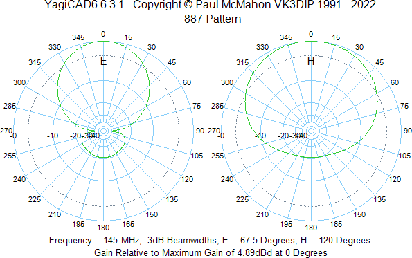
According to YagiCAD, the radiation pattern of the antenna is as follows:
For the boom, I use a piece of 16 mm outside diameter PVC electrical conduit pipe (“VP-rör” in Swedish). The boom is cut in the middle of the piece that holds the driven element so that the antenna can be further disassembled during transportation. The rear section is 347 mm long while the front one is 279 mm.

For the elements, I use 25 mm wide steel tape measure from Biltema, e.g. part number 16-2931. I taper the ends, round off the sharp edges with sand paper and put some sports tape over the edges both to protect from any remaining sharpness and to provide something for the screws in the spools to grab onto when rolling up the elements on the spools:

Throughout the design, M3 screws and nuts are used to hold the pieces together. Stainless screws and nuts should be used to prevent corrosion over time.
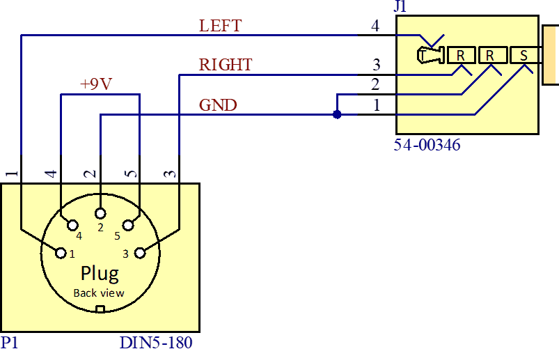
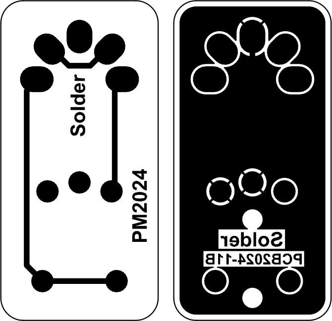
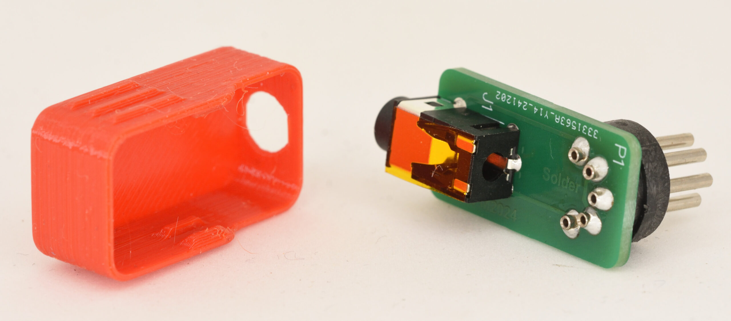
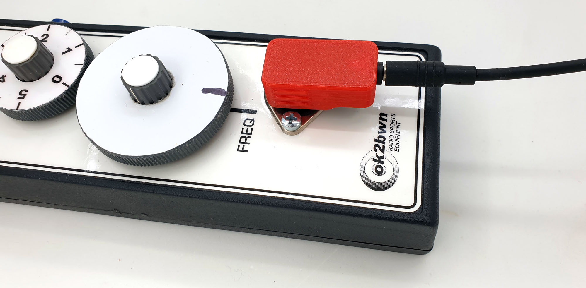
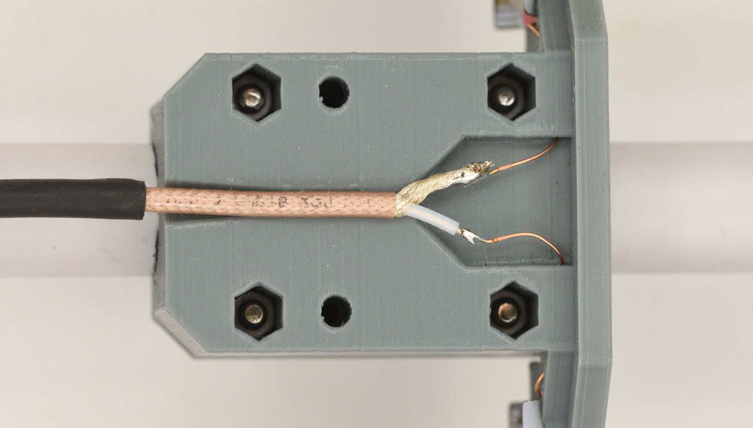
On the most recent antennas I have built, I have used a balun, CX2041ANLT, to interface the driven elements to the coax. The balun is soldered to a little PCB and placed in the recess in the part that holds the driven elements. A piece of standard perfboard could just as well be used instead of the custom PCB.

I have not checked if there is an actual difference in performance between antennas with this balun and without, like this:
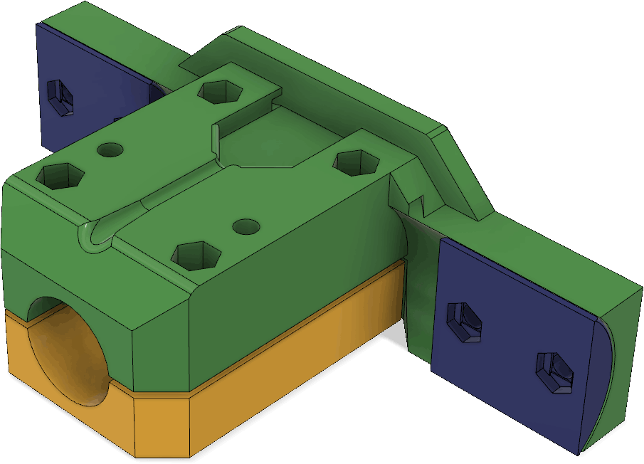
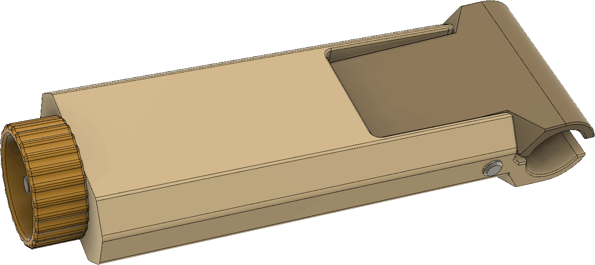
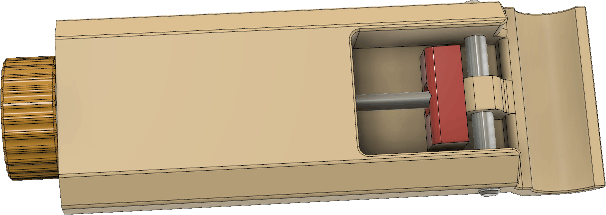
The nuts for the screws that hold the combined cover and strain relief are square ones that fit into slots in the side of the part. It can be helpful to use tack-it or some other sticky substance to hold them in place before putting in the screws.

See the article about the previous version for more details about the how the various pieces fit together.
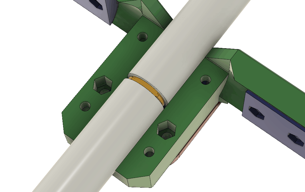
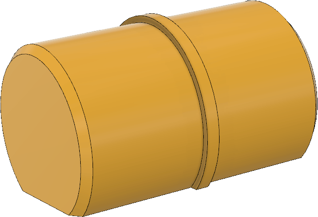
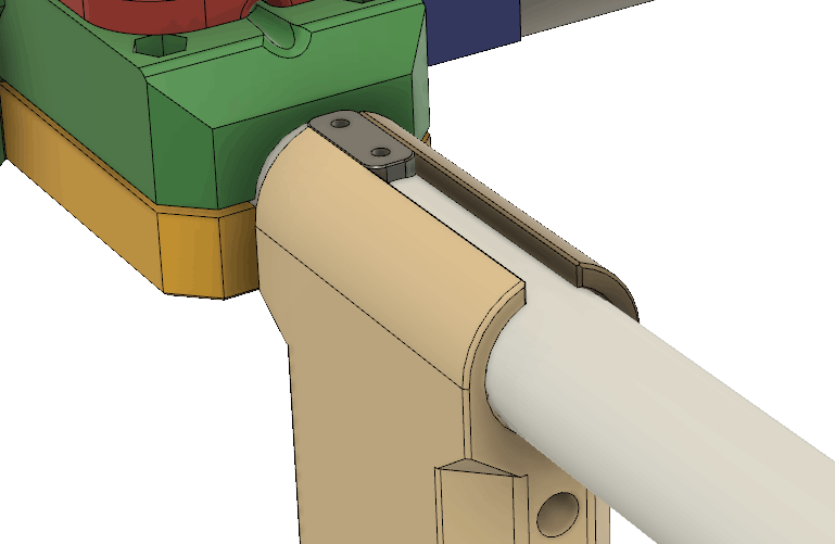
The grip of the handle around the boom is a little slippery. To avoid having the handle easily slip and rotate around the pipe while running, I made a little registration peg that can be glued onto the top of the pipe (preferably using epoxy). The gap in the handle clamp fits around the peg and prevents the handle from rotating. There are two holes in the peg where one can insert pieces of 3D filament to reinforce the glue joint. Corresponding holes obviously need to be drilled into the pipe as well. Be careful to place the peg in a suitable spot relative to the box with the electronics. There should be enough space behind it so that the handle is able to be pulled back and rotated during transportation or storage.
Handle pulled back and slightly rotated:

Handle in “use” position, locked from rotating by the peg.

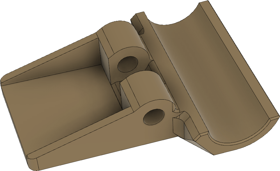
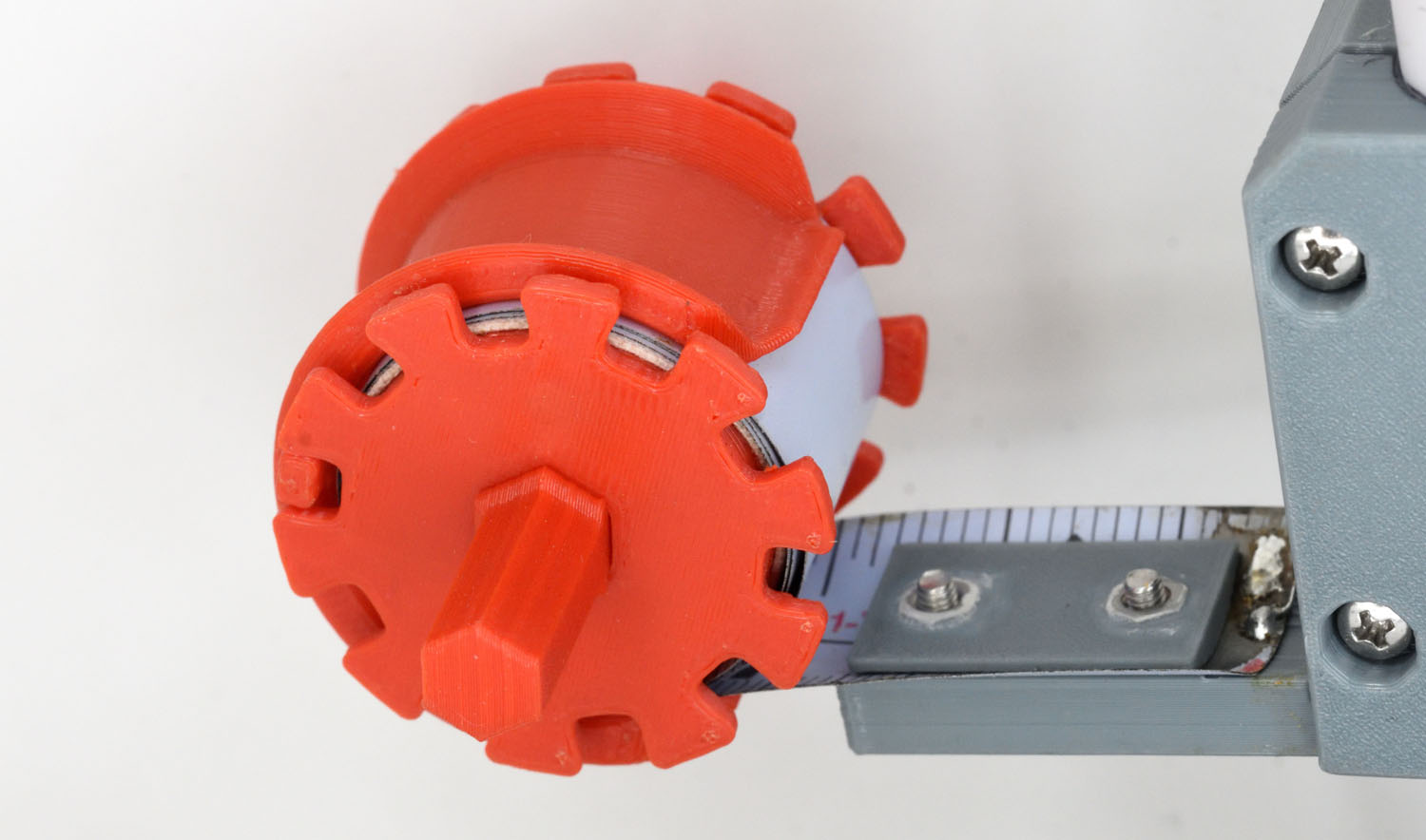
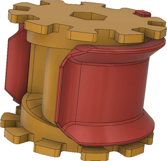
The spools and clamps that allow the tape measure elements to be rolled up for storage are perhaps the most intricate parts in this design. The spool and clamp together look like this:
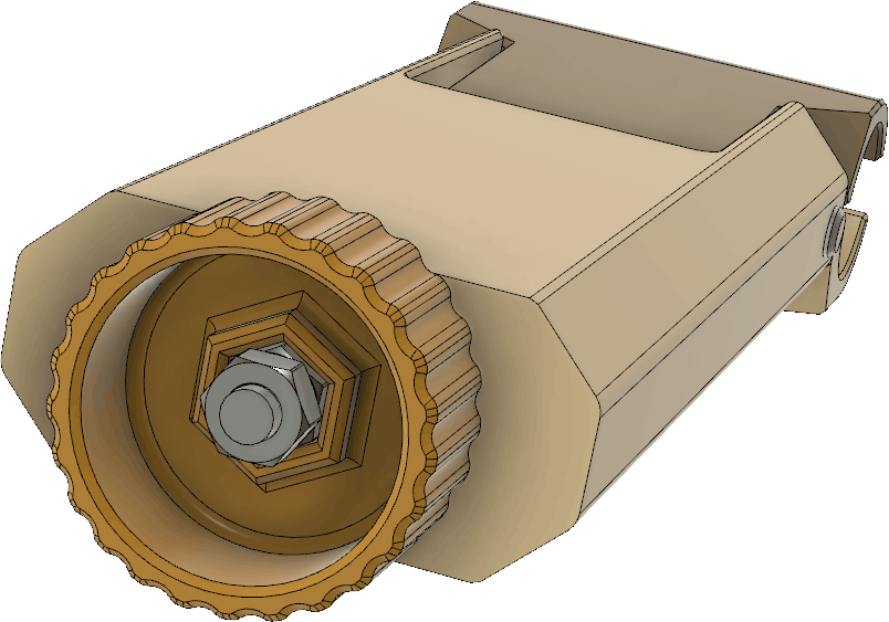
Six sets of spools/clamps are needed. To help when rolling up the tape measure onto the spool, there is also a hexagonal pin that fits in the center hole of the spool:
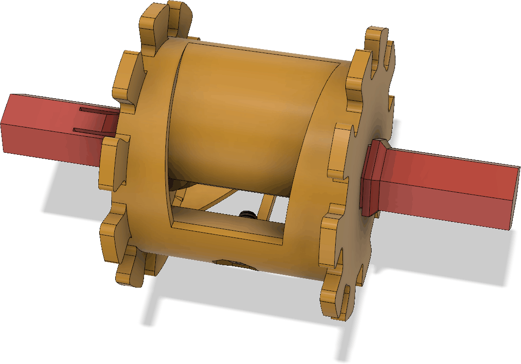
Only one such pin is needed per antenna as it can be moved between the spools. The M2.5 x 5 mm screw that is used as a hook for the tip of the tape measure when rolling it up is barely visible above.
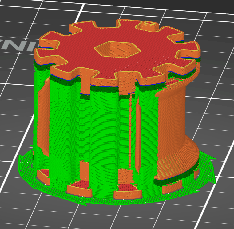
I now recommend to print the spools and spool clamps as separate pieces, instead of utilizing the spool clamp as part of the support for the spool (as was suggested in the previous article). This increases print time, but reduces the manual work separating the pieces and the support material. The spool clamp prints without support, but the spool requires it:

All other pieces print without support.
Two spools in use (with the pin in place in one of them) is shown below:

I printed the spools using neon-orange filament to make them more easy to spot in most environments and thus reduce the risk of losing them.