All posts by Per Magnusson

Rotary Encoder Routines for Teensy

In this post I describe some code I wrote to handle the input from an incremental rotary encoder connected to a Teensy. The code should work well also on an Arduino, provided the rotary encoder signals are connected to pins that have interrupt functionality.

A rotary encoder is great for many kinds of user interfaces. It physically looks like a potentiometer, but it is not limited to less than one turn. The output is digital, so it can relatively easily be interpreted by a micro controller, even one without a built-in analog to digital converter.

A rotary encoder.
A rotary encoder. Looks like a potentiometer, but it is digital.

The number of pulses per rotation can vary, but between 12 and 24 is common. An encoder contains two switches and if it is rotated clockwise, switch A closes before switch B for each “click” and if it is turned counter clockwise, switch B closes before switch A. This is called quadrature encoding since the two square waves are 90 degrees out of phase from each other.

By looking at the order in which the switches close, it is possible to determine in which direction the knob is turned. The figure below illustrates the waveforms, assuming the switches connects their pins to ground and that the two signals are otherwise pulled up to a positive voltage by pull-up resistors.
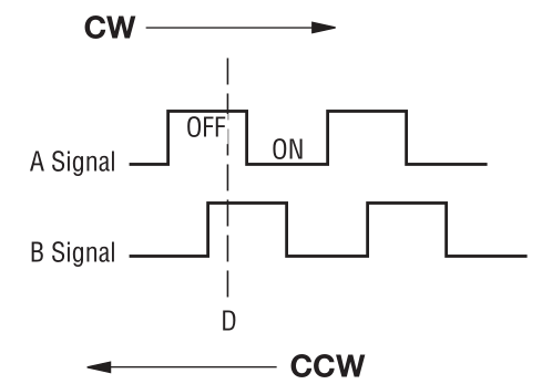
Quadrature waveforms from a rotary encoder.
Quadrature waveforms from a rotary encoder. “D” marks a detent or click state.

Below is a diagram showing how a rotary encoder and a push button (which is often integrated into the encoder) can be hooked up to a Teensy 3.1.
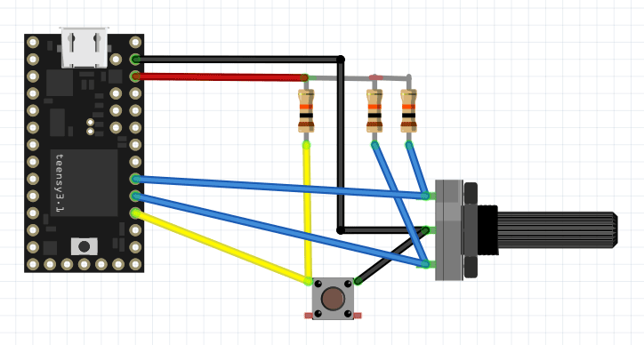
Encoder and button connected to pull-up resistors and a Teensy 3.1.

A problem when trying to use a rotary encoder as part of a user interface in an embedded application is that the pulses can be pretty short and it is important to not miss any, as that would mean missed rotations or even rotations detected in the wrong direction. Furthermore, like for almost all switches, there is also contact bounce that one must handle in some way. Typically, the processor has to do other things while also responding to input from the rotary encoder.

This means that it is often very hard or impossible to robustly interpret the signals from an encoder by polling the signals from within the main loop of the program. To get around this problem, one can instead use interrupt routines that are triggered when a signal from the encoder changes level. This is precisely what the code below does. It was written for a Teensy 3.1 (or 3.2), but should work on other platforms as long as the encoder signals are connected to pins with interrupt capability.

The following function call

attachInterrupt(digitalPinToInterrupt(rotAPin), ISRrotAChange, CHANGE);

sets up an the function “ISRrotAChange()” to be called every time the rotAPin changes state. This function in turn looks at the pin and sets the rotAval variable accordingly before calling the more complicated function UpdateRot() which contains a state machine that keeps track of what the rotary encoder is doing and increments or decrements the rotAcc (rotary encoder accumulator) variable when it has determined that the encoder has moved a notch. No debounce timer is necessary since it is pretty safe to assume that the bounces of one switch will have died out before the next switch will be activated.

The rotAcc variable is changed only after the second signal becomes activated (low) while the first signal is still active since it is pretty common that one signal is activated and later deactivated without the second signal becoming active. This happens when the operator rotates the knob a fraction of a notch and then lets it return to the original position without going all the way to the next notch.

The main loop must not look directly at the rotAcc variable since it can be changed at any point within the program by an interrupt. It is only safe to access it while interrupts are disabled, so accesses have to be surrounded by cli() (clear interrupt enable bit) and sei() (set interrupt enable bit) function calls. This is done in the GetRotAcc() function which thus provides a convenient way of safely looking at the value of the accumulator. The interrupt service routines (ISRs) themselves do not need to mess with cli() and sei() when accessing the interrupt state variables since interrupts are automatically temporarily disabled while servicing an interrupt.

Since the global variables used by the interrupt routines can be changed at any point within the course of the main program, they have to be be declared with the keyword “volatile” to prevent the compiler from making optimizations that assume that they behave like normal variables that will never magically change under the feet of the main program code.

Expand the Teensy code
[cpp] /* Interrupt driven rotary encoder routines.
   Target: Teensy 3.1
   
   Written by Per Magnusson, http://www.axotron.se
   v 1.0 2015-11-15
   This program is public domain.
*/

// Rotary encoder push button pin, active low
static const int pushPin = 16;
// Rotary encoder phase A pin
static const int rotBPin = 17;
// Rotary encoder phase B pin
static const int rotAPin = 18;

#define DEMO 1

// Rotary encoder variables, used by interrupt routines
volatile int rotState = 0;
volatile int rotAval = 1;
volatile int rotBval = 1;
volatile int rotAcc = 0;

void setup()
{
  Serial.begin(57600);

  pinMode(rotAPin, INPUT);
  pinMode(rotBPin, INPUT);
  pinMode(pushPin, INPUT);
  attachInterrupt(digitalPinToInterrupt(rotAPin),
    ISRrotAChange, CHANGE);
  attachInterrupt(digitalPinToInterrupt(rotBPin),
    ISRrotBChange, CHANGE);
}

void loop()
{
  static int oldRotAcc = 0; // Remember previous state
  int newRotAcc;
 
  // Do not look directly at the rotary accumulator variable,
  // it must be done in an interrupt safe manner
  newRotAcc = GetRotAcc();

  if(!digitalRead(pushPin)) {
    // The button was pushed.
    // Button detection is not interrupt driven, but detection of the
    // rotary encoder movements goes on also in the busy way below.
    Serial.println("Button down");
    delay(10); // Debounce
    while(!digitalRead(pushPin))
      ;
    delay(10); // Debounce
    Serial.println("Button up");
  } else if(newRotAcc != oldRotAcc) {
    // The encoder was rotated at least one step.
    Serial.println(newRotAcc);
    oldRotAcc = newRotAcc;
  }
}

// Return the current value of the rotaryEncoder
// counter in an interrupt safe way.
int GetRotAcc()
{
  int rot;
 
  cli();
  rot = rotAcc;
  sei();
  return rot;
}

// Interrupt routines
void ISRrotAChange()
{
  if(digitalRead(rotAPin)) {
    rotAval = 1;
    UpdateRot();
  } else {
    rotAval = 0;
    UpdateRot();
  }
}

void ISRrotBChange()
{
  if(digitalRead(rotBPin)) {
    rotBval = 1;
    UpdateRot();
  } else {
    rotBval = 0;
    UpdateRot();
  }
}

// Update rotary encoder accumulator.
// This function is called by the interrupt routines.
void UpdateRot()
{
  // Increment rotAcc if going CW, decrement it if going CCW.
  // Do not increment anything if it was just a glitch.
  switch(rotState) {
    case 0: // Idle state, look for direction
      if(!rotBval) {
        rotState = 1;  // CW 1
      }
      if(!rotAval) {
        rotState = 11; // CCW 1
      }
      break;
    case 1: // CW, wait for A low while B is low
      if(!rotBval) {
        if(!rotAval) {
          rotAcc++;
#ifdef DEMO          
          // Remove this when not in demo mode
          Serial.print(" right ");
#endif
          rotState = 2; // CW 2
        }
      } else {
        if(rotAval) {
          // It was just a glitch on B, go back to start
          rotState = 0;
        }
      }
      break;
    case 2: // CW, wait for B high
      if(rotBval) {
        rotState = 3; // CW 3
      }
      break;
    case 3: // CW, wait for A high
      if(rotAval) {
        rotState = 0; // back to idle (detent) state
      }
      break;
    case 11: // CCW, wait for B low while A is low
      if(!rotAval) {
        if(!rotBval) {
          rotAcc–;
#ifdef DEMO
          // Remove this when not in demo mode
          Serial.print(" left ");
#endif
          rotState = 12; // CCW 2
        }
      } else {
        if(rotBval) {
          // It was just a glitch on A, go back to start
          rotState = 0;
        }
      }
      break;
    case 12: // CCW, wait for A high
      if(rotAval) {
        rotState = 13; // CCW 3
      }
      break;
    case 13: // CCW, wait for B high
      if(rotBval) {
        rotState = 0; // back to idle (detent) state
      }
      break;
  }
}
[/cpp]


In this demo version of the code, status information is sent back over the USB serial port so that a terminal window (e.g. the one in the Arduino environment) can display it. The texts “left” or “right” are printed by the ISR when it changes the value of rotAcc and the main loop prints the value of rotAcc when it detects that it has changed.

The main loop handles the push button. This is done through normal polling. A delay is used to filter out contact bounces. While the button is held down, the main loop is stuck and cannot print updated rotAcc values, but the ISR routines happily execute if the encoder is rotated, so the “left” and “right” strings can still appear while the button is pressed.

Here is an excerpt from a terminal session:

 right 1
 right 2
 right 3
 right 4
 right 5
 left 4
 left 3
Button down
 right  right  right  right  left  right Button up
7
 right 8
 right 9
 left 8
 left 7

The encoder was rotated clockwise (CW) five steps (right 1 to right 5) and then counter clockwise (CCW) by two steps (left 3). Then the button was pushed and held down (Button down) while the encoder was rotated four notches CW, one CCW and one CW  before the button was released. After this the main loop resumed and detected that the rotAcc value had changed to 7. Then the encoder was rotated two more notches CW and two CCW.

When not using this to demo the functionality of these specific routines, the Serial.print() statements in the interrupt routines should be removed, either by not #defining DEMO or by removing those lines of code completely.
Solution to why Windows 10 randomly wakes up from hibernation

Here is another issue I have been having since upgrading to Windows 10: I often find that the computer has woken up from hibernation, which is of course irritating since it unnecessarily consumes power. I did some googling and found a number of things that could be the cause, like the mouse, keyboard or network interface being able to wake the computer up. Turning all of these off did however not stop the computer from waking up.

Also, a recommendation was to issue the following command in a cmd window to figure out why the computer woke up:

C:\WINDOWS\system32>powercfg /lastwake
Wake History Count - 1
Wake History [0]
  Wake Source Count - 0

In my case the response unfortunately says nothing about why the computer woke up, which seems like a major shortcoming.

Then I tried the following:

C:\WINDOWS\system32>powercfg /waketimers
Timer set by [SERVICE] \Device\HarddiskVolume2\Windows\System32\svchost.exe (SystemEventsBroker) expires at 15:46:51 on 2015-09-27.
  Reason: Windows kör den schemalagda aktiviteten NT TASK\Microsoft\Windows\Media Center\mcupdate_scheduled som kräver att datorn aktiveras.

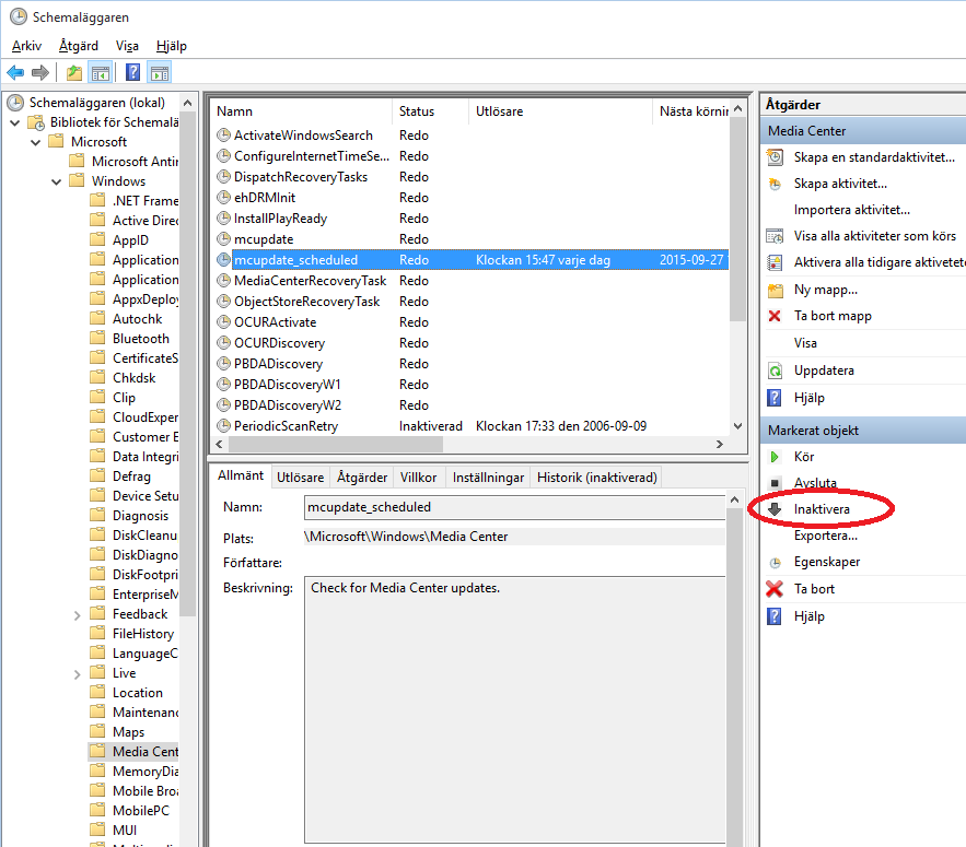
This did give a useful hint since it told me that mcupdate_scheduled was set to wake the computer up at 15:46:51 the next day, presumably to update Media Center. I do not want the computer to wake up to install updates, so I found out that scheduled tasks can be controlled by “Schedule tasks” (or “Schemalägg aktiviteter” as it is called in my Swedish W10 installation). In it I was able to dig down to Media Center and disable its daily checking for updates, see screenshot below (again, it is from my Swedish installation, but I guess it is it trivial to figure out how to do the same thing in an English W10).

Media Center update scheduling
Media Center update scheduling.

I clicked the circled Deactivate (“Inaktivera”) button to disable the scheduled updates and after this the powercfg /waketimers gave the following response:

C:\WINDOWS\system32>powercfg /waketimers
There are no active wake timers in the system.

Another way of checking for tasks that could wake up the computer is to run Power Shell and the following command:

PS C:\Users\Per> Get-ScheduledTask | where {$_.settings.waketorun}

TaskPath                                       TaskName                          State
--------                                       --------                          -----
\Microsoft\Windows\.NET Framework\             .NET Framework NGEN v4.0.30319... Disabled
\Microsoft\Windows\Media Center\               mcupdate_scheduled                Disabled

Apparently, no task is currently about to wake the computer up. Good.

I also found the following Power Shell command that can be used to disable scheduled wake ups:

Get-ScheduledTask | ? {$_.Settings.WakeToRun -eq $true -and $_.State -ne "Disabled"} | % {$_.Settings.WakeToRun = $false; Set-ScheduledTask $_}

I hope that this will be the end of the computer waking up all by itself. If it is not, I will continue to run the above commands again to see if any new wake timers have popped up.

Update 2016-01-04

Even though the frequency of unwanted wakeups seemed to be much reduced by the above measures, they sometimes occured anyway. Maybe I have just not found and disabled enough things that can cause a wakeup. I have given up on hunting these down, so instead I connected the computer and monitor to a power strip with a switch that I use to remove power from the computer once it has started to hibernate. As long as I remember to turn off the switch, this is guaranteed to prevent the computer from waking up while in hibernation.

Update 2016-10-01

A couple of times I have noticed that my mouse has reverted to being able to wake the computer up. Maybe this happens during some Windows updates. Some of the spurious wake-ups have probably been due to e.g. the scroll wheel on the mouse moving half a notch by itself which might happen if it accidentally was left between two notches. A straightforward way to verify if this can happen is to put the computer into hibernation and then start moving, clicking and scrolling on the mouse. Also try the keyboard while you are at it. To disable wakeup from mouse or keyboard, go to the device manager, right click on the device, select the Power Management tab and disable the wake-up option.

Another thing I have found that can wake the computer up is if I connect am mp3-player to a USB hub while the computer is hibernating, but I have found no setting to disable this.

Still, the trusted old power switch on the power strip without any software involved remains the most reliable method of preventing the computer from waking up when it should not.

Update 2018-03-24

It seems like Windows repeatedly starts allowing mice and keyboards to wake the computer up. One way to check which devices can currently wake the PC up is to issue the following command in a cmd window:

powercfg -devicequery wake_armed

Then one can go into device manager, right click on the offending devices, select Properties and in the Power management tab disable the wakeup capability.

It would be really nice if one could set a flag somewhere to never ever enable anything but the power button to wake the computer up to avoid the PC unnecessarily being on and consuming power for long periods when it is not used.

Macro Photography Using a Macro Coupler

Sometimes I want to take closeup photos of printed circuit boards to e.g. document broken or incorrectly assembled components. Given the small size of many components (like 0402 or even 0201), a high degree of magnification is often required. I have a 150 mm Sigma macro lens that can do 1:1 magnification from subject to detector, but this is not always good enough, so I was looking for another solution, preferably going up to a magnification of about 6:1 so that a 4 mm subject would fill up the view of my Nikon D300. Also, I did not want to spend too much on new equipment as this is something I do not do very often.

It turns out that there are a number of ways to make existing lenses more suited for macro photography, namely:

  • extension tubes (reduces minimum focus distance)
  • macro bellows (essentially long and adjustable extension tubes)
  • close-up lenses to put on the front of existing non-macro lenses
  • reversing rings to mount lenses backwards
  • macro couplers to mount one lens backwards in front of another

I did some quick calculations (using information from this page) and figured out that extension tubes or bellows would not give me much of additional magnification. They need to be very long to have much of an effect on long lenses and with shorter lenses the focus distance for large magnification becomes very small.

According to a formula on https://en.wikipedia.org/wiki/Close-up_filter, a close-up lens (or close-up filter as it is also called) needs to have a power of 20 diopters to give a 6:1 magnification on my 70-300 mm lens and 33 diopters on my 150 mm macro lens. The problem is that such strong close-up lenses seem to be rare and if they exist they are probably not very sharp.

To get magnification from mounting a single lens in reverse, the focal length needs to be short. From a 50 mm lens, the expected magnification is probably only about 1:1, so this did also not seem like a very good option.

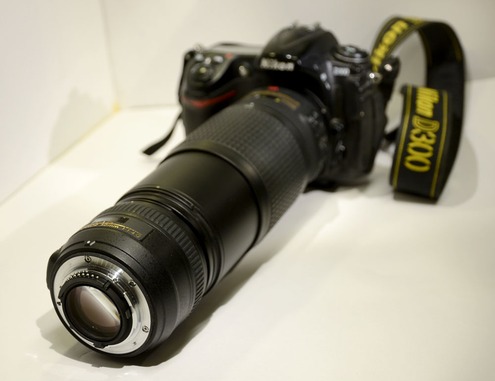
The solution I opted for was instead to use a macro coupler to mount my 50 mm f/1.4 lens backwards in front of my 70-300 mm zoom. A 50 mm lens has a power measured in diopters of 1/(0.050 m) = 20 diopters, so it will act as a close-up lens that powerful, giving a magnification at the 300 mm setting of about (300/50):1 or 6:1.

Since the 50 mm lens has a 58 mm thread and the zoom has a 67 mm thread, I needed a step-up ring from 58 to 67 mm and a 67-67 mm macro coupler ring. I found inexpensive ones at a local Internet shop, http://kaffebrus.com/step-up-ringar-121.html and http://kaffebrus.com/adapterring-koppling-122.html. Total cost was 147 kr or about $18.

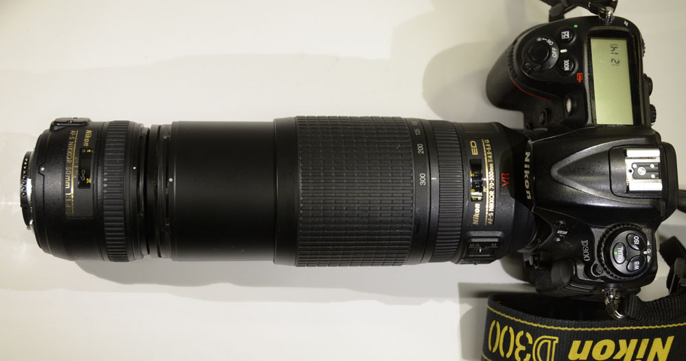
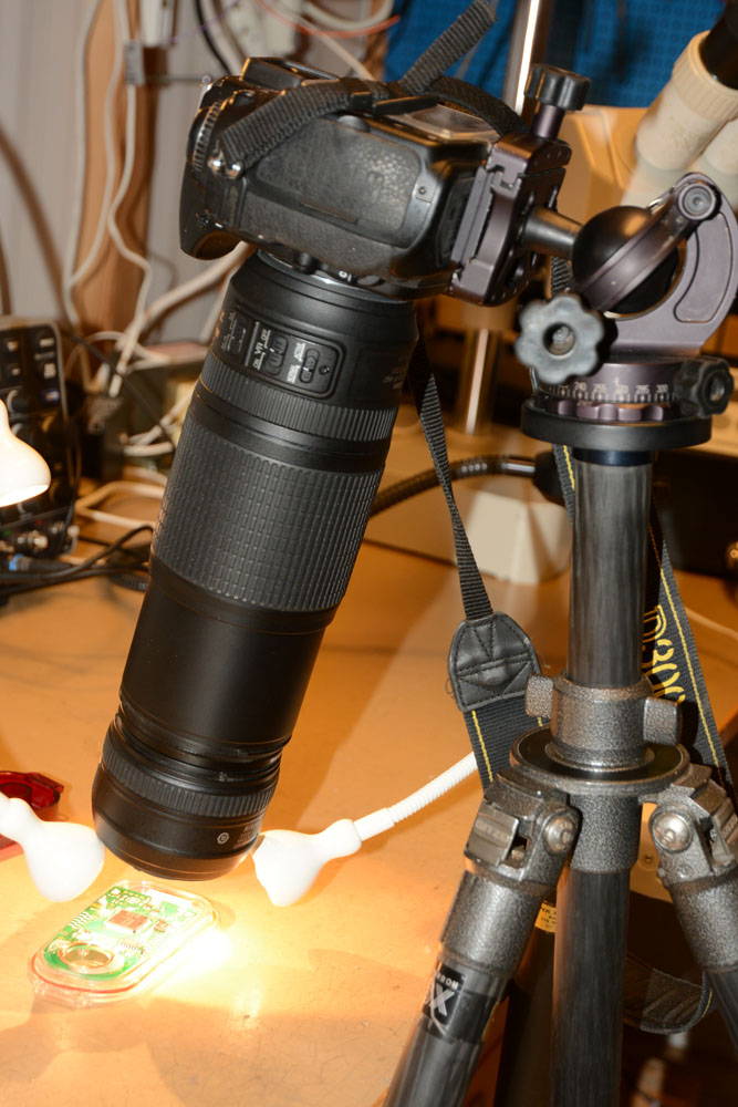
This is what it looked like when I used the rings to mount the short lens in backwards in front of the zoom lens on the camera:

50 mm lens in front of 70-300 mm lens.

DSC_6707_sm

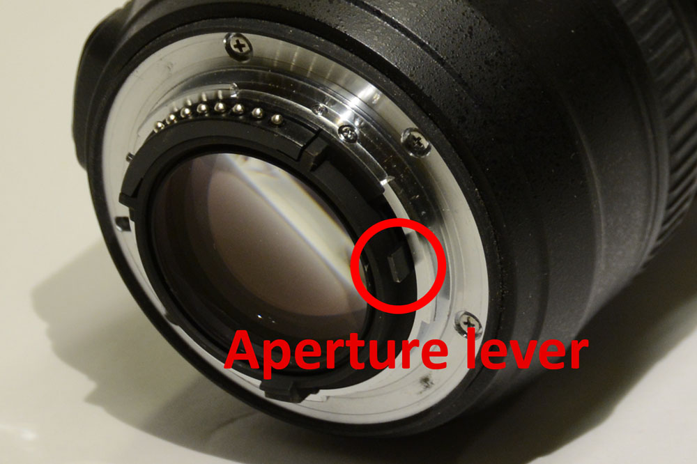
One thing that immediately becomes apparent when looking into the viewfinder is how dark it is. This is due to the fact that the 50 mm lens goes to minimum aperture when it is not connected to a camera, so it lets in very little light. There is no aperture ring on this lens, but there is a small lever in the mount that one can manually pull to increase the aperture and I found that it is possible to put a piece of tape on the lever to fix it in a desired position. Small aperture is good to get maximum depth of field, but it can be hard to see the subject unless the lighting is very bright, so taping the lever to maximum aperture while composing the scene and then removing the tape before taking the shot might be a good idea.

Aperture lever
Aperture lever

The aperture of the zoom lens seems to not be very critical, but it should be open enough to not cause vignetting. Also, zooming out far away from 300 mm causes vignetting, so the setup is mostly useful at or close to 300 mm.

It is of course necessary to use a tripod and in order to get as sharp photos as possible, one needs to take every reasonable step to reduce vibrations, like using a remote shutter release cord and the mirror-up mode so that the mirror does not cause camera shake.

A future improvement would be to build a focusing rail and apply focus stacking to get a greater depth of field. Building a stepper motor controlled focusing rail could be a fun project.

Below are some test photos I have taken with the setup.

Millimeter lines on the scale of a caliper. The field of view is about 4 mm wide.
Detail from a 100 kr bill.
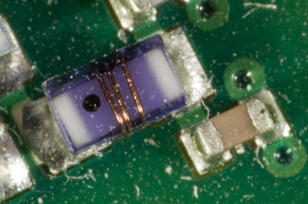
An 0603 inductor and an 0402 capacitor.
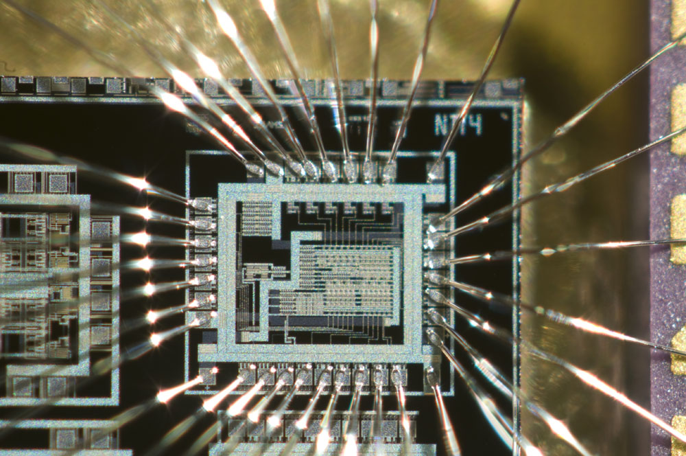
An integrated circuit I made around 1995 as a project at the university. The technology is 0.8 µm CMOS.
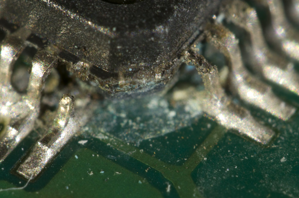
Pins of a TQFP package, of which one is broken and another is damaged.
Pins of a TQFP package (0.5 mm pitch), of which one is broken and another is damaged.
Detail from a flower.
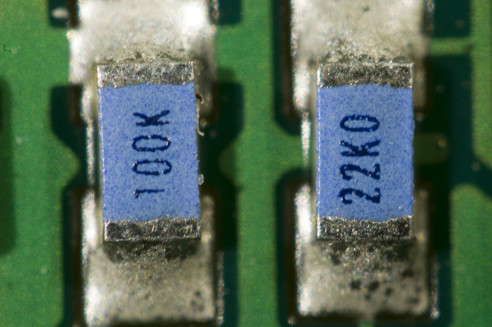
Two 0603 resistors.
Two 0603 resistors.
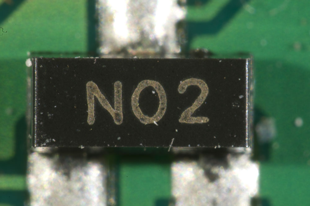
A SOT23 component.
An SOT23 component.