All posts by Per Magnusson

Hur man uppdaterar batteristatus i en SI-enhet efter batteribyte

This post is in Swedish, but the same information is available in English on the last page of this PDF from Sportident.

Om man har bytt batteri i en Sportident-enhet så är det en bra idé att tala om för enheten att det nu sitter ett nytt batteri med full kapacitet i enheten så att den kan försöka hålla reda på hur mycket kapacitet som återstår. Som bekant så använder man programmet  SPORTident Config+ för att programmera SI-enheter, ställa tiden, uppdatera firmware mm, men tyvärr så kan man i vanliga fall inte komma åt funktionen för att ställa om batteristatusen. Kanske anser Sportident att funktionen är för riskabel att ha allmänt tillgänglig, men det går ganska lätt att slå på den. Så här gör man:

Högerklicka på genvägen till SPORTident Confg+ på skrivbordet. Då dyker en meny upp som ser ut något i stil med detta:
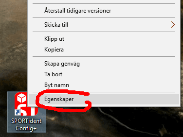
Menyn som kommer upp vid högerklick på Config+ikonen.

Välj alternativet “Egenskaper” längst ned. Nu dyker följande fönster upp:
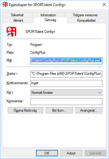
Dialogrutan med egenskaper för genvägen.

Tricket man behöver göra är att lägga till texten −−service sist i rutan “Mål:”. Enklast görs detta på följande vis:

  • Tryck på pil höger så att den blåmarkerade texten avmarkeras och markören hamnar sist i rutan.
  • Tryck mellanslag.
  • Skriv in −−service (dvs två minustecken och sedan ordet service utan några mellanslag). Så här bör det se ut:
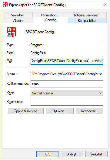
Flaggan −−service har lagts till.
  • Tryck OK för att stänga rutan.

Om man nu startar SPORTident Config+ från den ändrade genvägen så finns plötsligt den nya menyn Service högst upp:
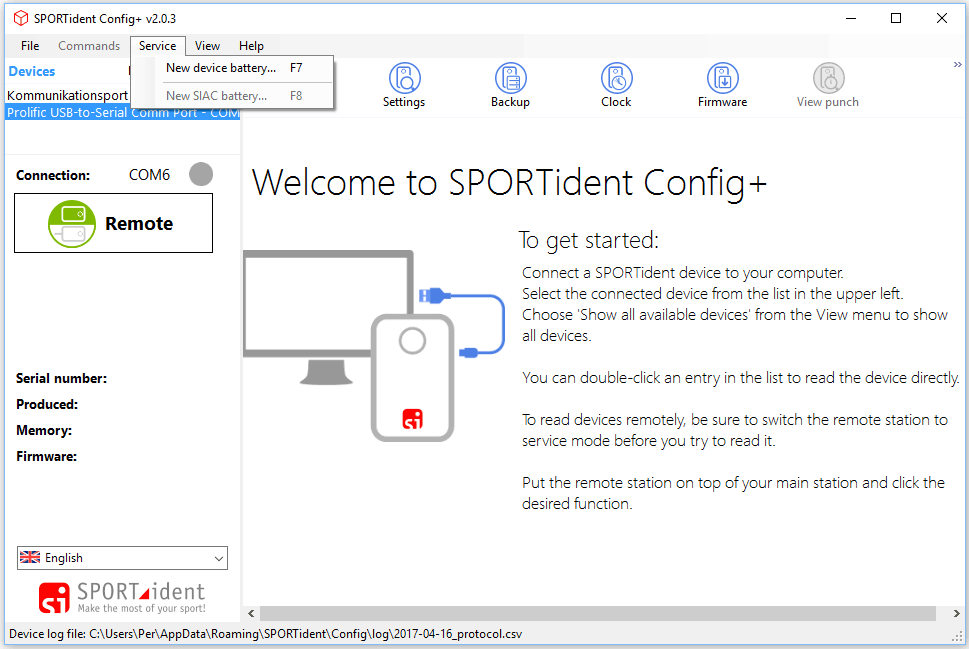
Service-menyn har dykt upp.

Om man väljer alternativet “New device battery” så får man upp följande:
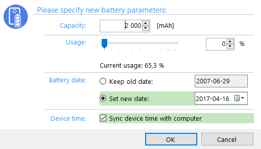
Fönstret för att uppdatera batteristatus

På en BSF8 med vanligt litet batteri (1/2 AA) så är det normalt 1000 mAh man ska mata in och om man precis satt in ett nytt batteri så ska såklart Usage stå på 0%. På en BSM7 (med sladd) med batteri i AA-storlek är det normalt 2000 mAh i batterikapacitet.

Mer information om andra saker att tänka på när man byter batteri finns i följande dokument från SportIdent:
Battery exchange in BSF7 and BSF8 stations

Improving the Depanelization Process

In the previous post, I wrote about using my CNC mill to depanelize PCBs. One issue  I had was that the boards were not cleanly separated from the panel since they moved away as soon as the mill broke through the tab connecting them to the panel, leaving a pointy feature.

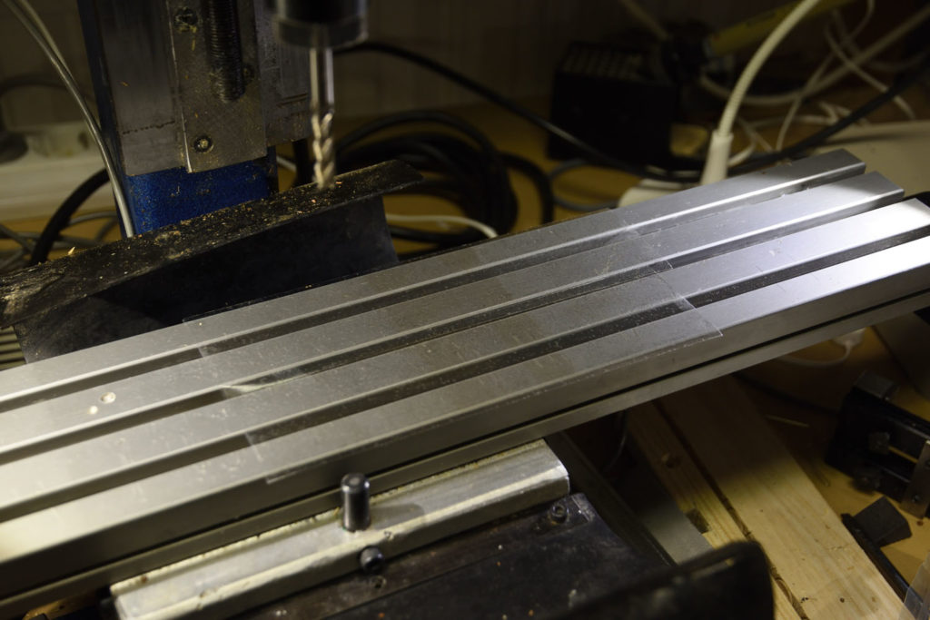
I tried to improve this by using double sided tape to keep the boards in place:

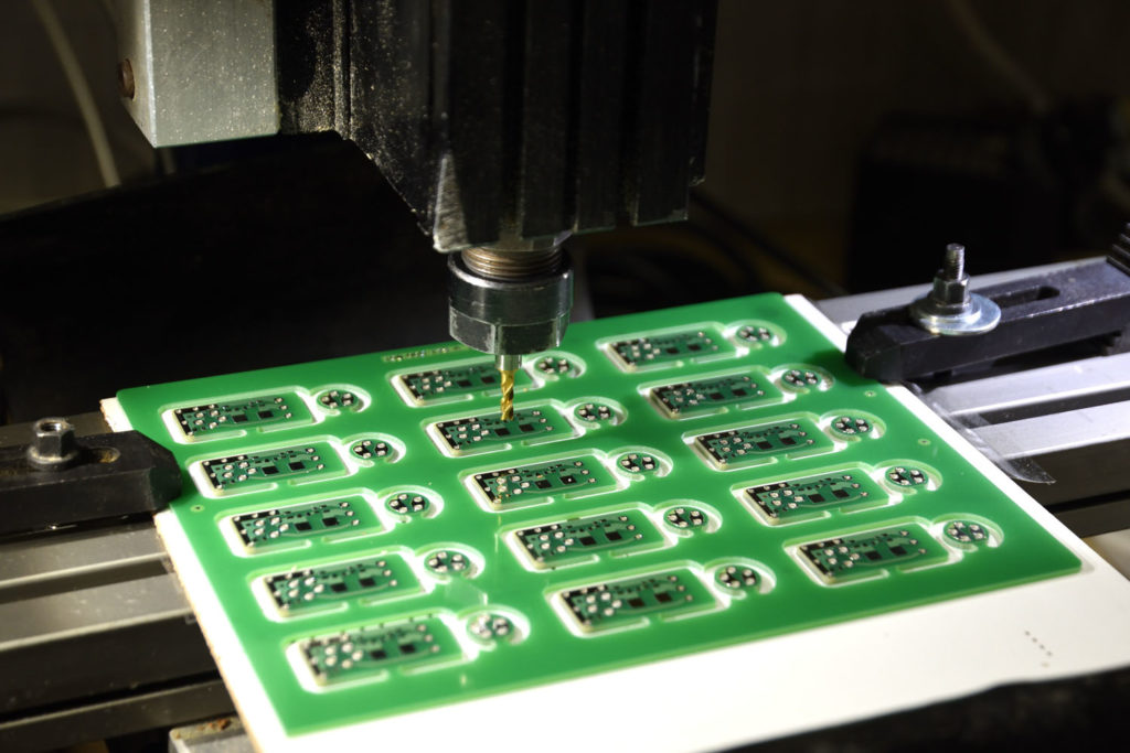
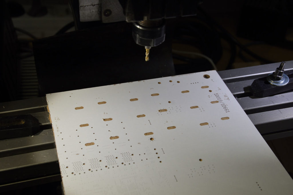
Double sided tape on the CNC bed to keep the sacrificial board firmly in place.
The sacrificial (MDF?) board on top of the tape. The glossy surface will make it easier to remove the tape.
The PCB panel has been secured in place. There is double sided tape between it and the board. Two clamps aid in the workholding.
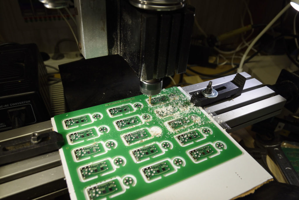
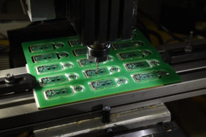
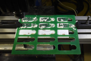
Milling in progress. Some boards still get loose, but some stay in place.
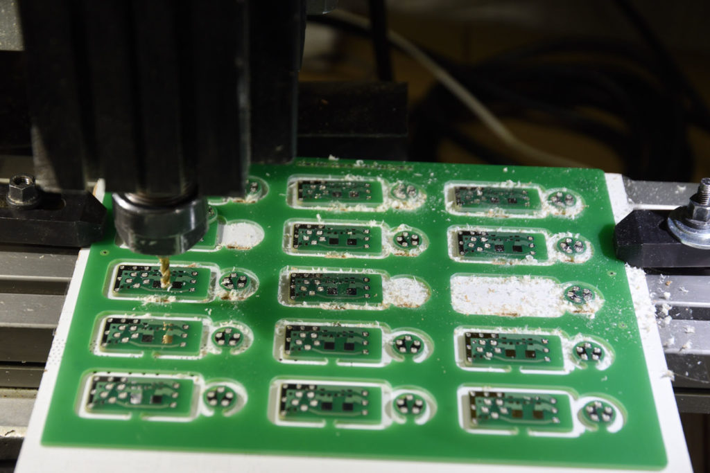
Separation of the upper three rows of boards complete.
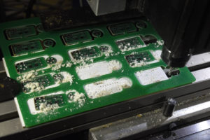
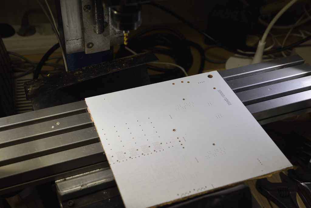
The mill is not big enough to reach all boards in one setup and I tried to reuse the tape when separating the lower two rows. Due to the dust from the initial milling getting into the adhesive, this was not a great idea. Using new tape would have been better.
The sacrificial board after the panel and the top side tape have been removed. The board can be reused. The pattern created by the mill can be used to position the next panel. Even better would be to have guide holes in the PCB panel and run a mill program to create corresponding holes in the sacrificial board to aid in precise positioning of the panel.

In summary, using double sided tape to aid in the workholding is a promising idea. With the small board in this panel it was however only semi-successful since the adhesive has very little area to attach to and the PCB surface is a bit uneven due to the trace pattern. On larger boards it will probably work better.

Depanelizing PCBs with the CNC mill

One use for the CNC mill I wrote about in the previous post is to depanelize PCBs, i.e. to mill out individual printed circuit board from a larger panel.

Panel before depanelization

My first attempt att doing this was with a panel of PCBs that were already almost completely routed out from the panel. Only a small tab remained that held each board to the panel. I had designed the panel with “mouse bites” (a row of small holes) along the board edges towards the tabs, but due to an error on behalf of the PCB manufacturer, these holes were never drilled. (I did later receive a new set of panels with this error corrected, without extra cost.)

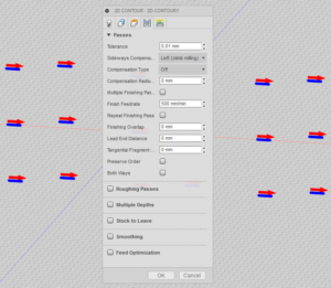
Based on the CAD files for the panel, I made a drawing in DraftSight with a center line for the mill through each tab. I imported the resulting DXF file into Fusion 360 (via the Upload feature) and created gcode using the 2D contour method with compensation set to Off to make the tool follow the center of the line. Using Fusion 360 for this is severely overkill, but it works.

2D contour setup with compensation set to Off.

I put the origin of the gcode in a place that was easy to locate on the board so that I could zero the coordinate system of the mill properly. I also took care to align the edge of the panel with the edge of the mill table. Since the panel was taller than the working area of the mill, I could not make a single program that would depanelize all boards. Instead I made a program that cut out three of the five rows and ran it twice with the panel appropriately moved on the table between the runs.

I did run into a couple of problems though:

Uploading the small DXF file to Fusion 360 took a long time (several minutes). I later realized that there is a menu alternative under the Insert menu that might have worked better.

Another and more serious issue is that Fusion 360 decided to silently interpret the DXF file as if the units was cm (who in their right mind draws in cm???). My drawing was of course in mm, so the resulting gcode instructed the CNC mill to move ten times longer than intended. I did not discover this until the mill started to move in unexpected ways that might have easily broken off the tool, had I not been quick enough to stop it and figure out what was going on. The Insert/Insert DXF function allows the user to select the unit, so this seems like a much better option to get DXF into Fusion than  the Upload function. I will use that method in the future.

Once the mm/cm issue was resolved and new gcode was created I successfully depanelized the PCBs:

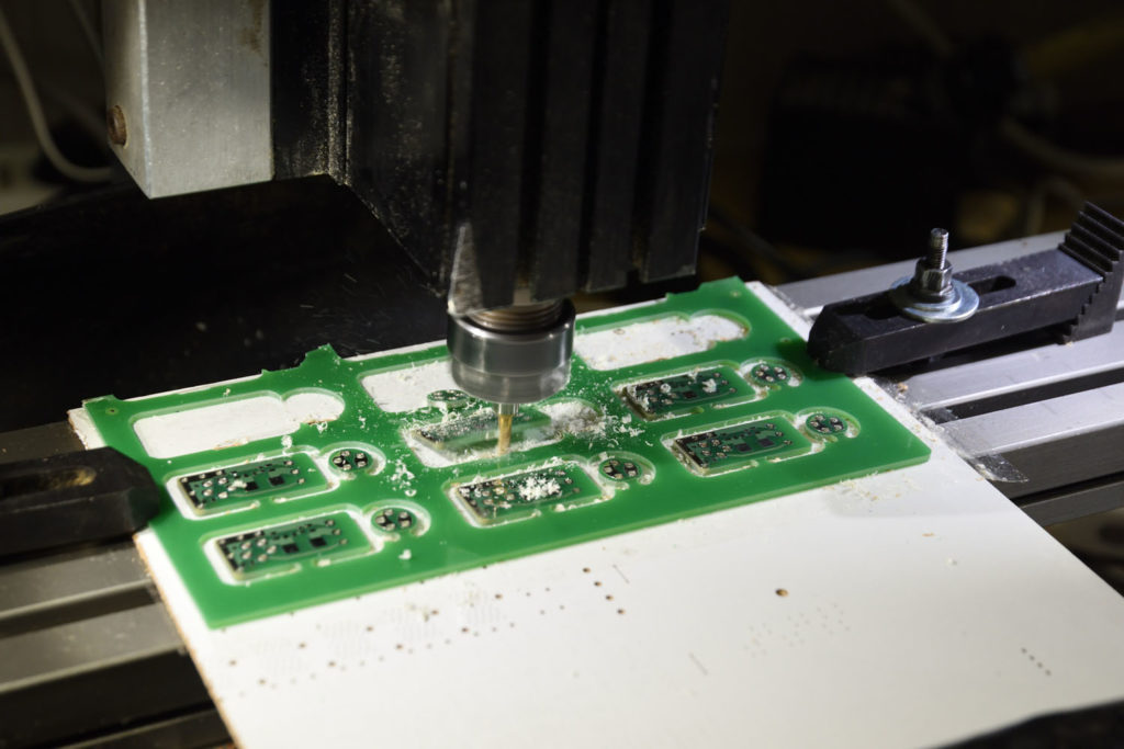
The program has been run to depanelize three rows of PCBs.
The final two rows of PCBs have been separated from the panel.
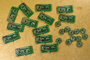
The resulting small boards. Some manual filing is necessary to remove the burrs.

An artifact that is obvious on the individual PCBs is that a pointy remnant of each tab is still present. This is because the PCBs are only held in place by the tab, so when the tab is almost cut through, it bends and the board is pushed away so that the final part of it is not removed. The way to prevent this would be to somehow hold the PCBs in place independently of the tabs, but this is tricky, especially with the very small PCBs in this panel.