Monthly Archives: July 2015

Sportident Station with Pulverized Power Pins

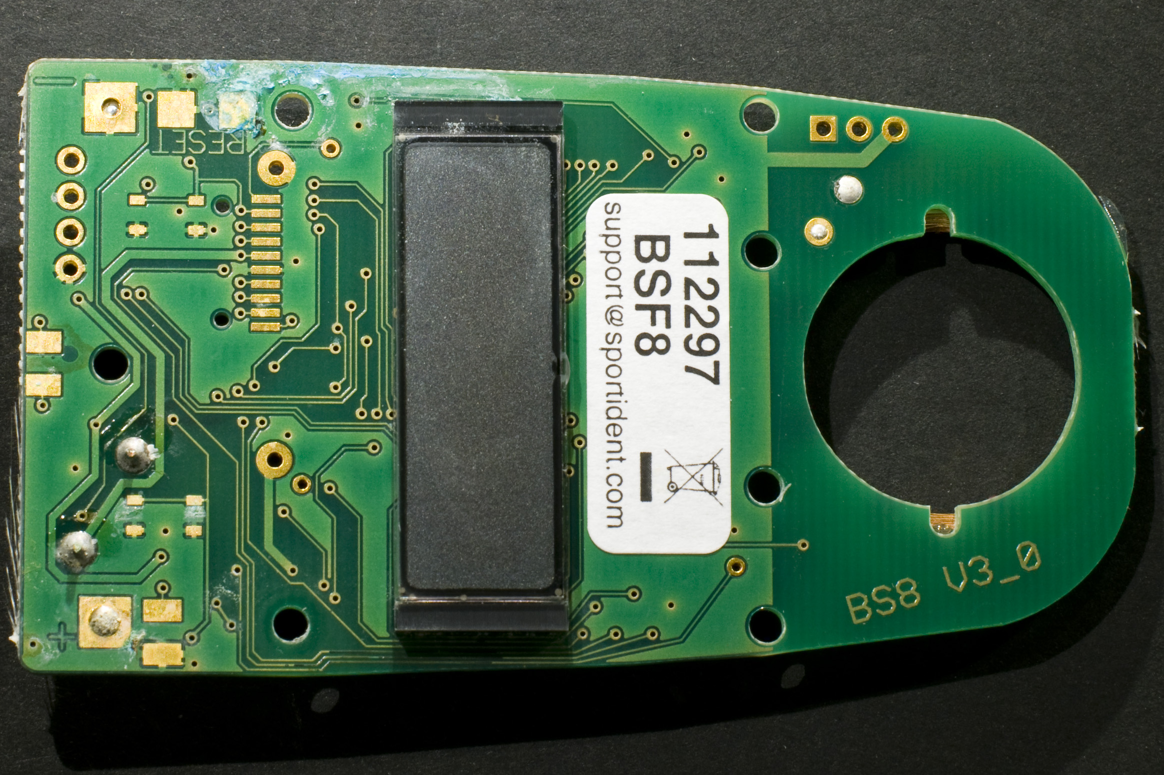
While I was updating the firmware of many BSF8 Sportident stations to 6.23, I had a weird failure on a unit with serial number 112297. It may or mat not be related to the voltage measurement bug described on the last page of the release notes of the 6.23 firmware, http://www.sportident.com/images/software/si_boot_firmware_623_release_notes_en.pdf. If I recall correctly, the sequence of events was this:

  • The unit showed a very low voltage reading (2 V or so) and upgrading to 6.23 failed.
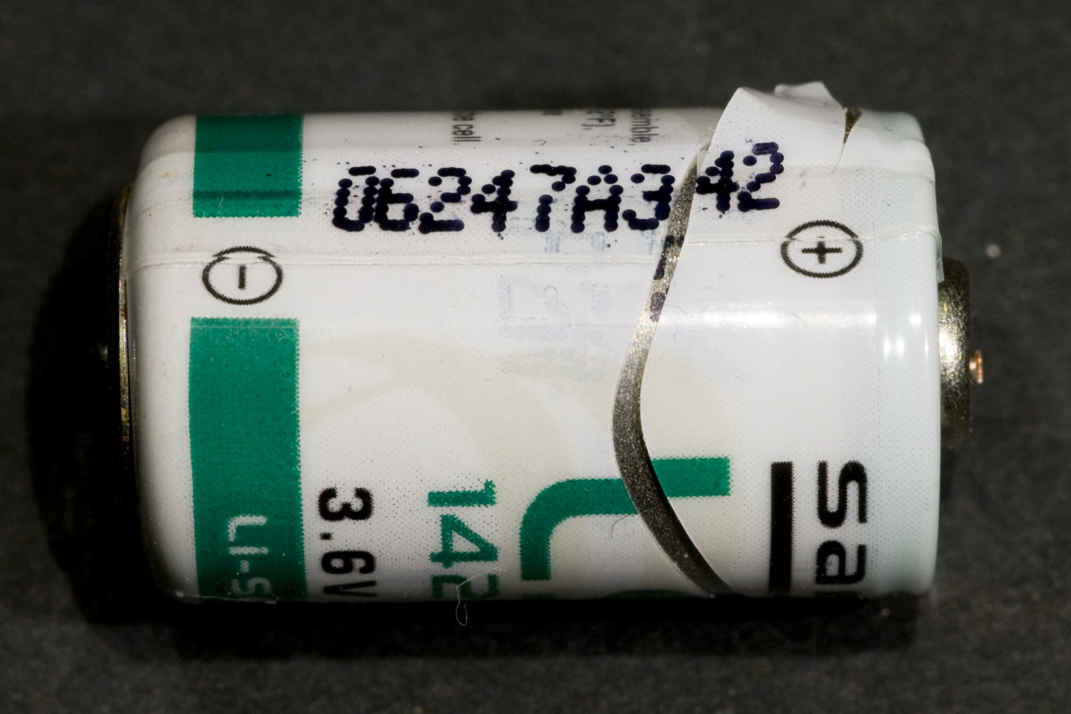
  • I opened it up to change the battery and measured the battery voltage with a DMM. It was indeed 2 V or thereabout.
  • Then the station died completely (I am unsure exactly when in the sequence of events this happened, maybe later).
  • I might then have desoldered the old battery and connected the station to an external power supply (3.5 V, limited to about 100 mA) to test it before I connected a new battery. I think I at first got it to work, but then it stopped working again.
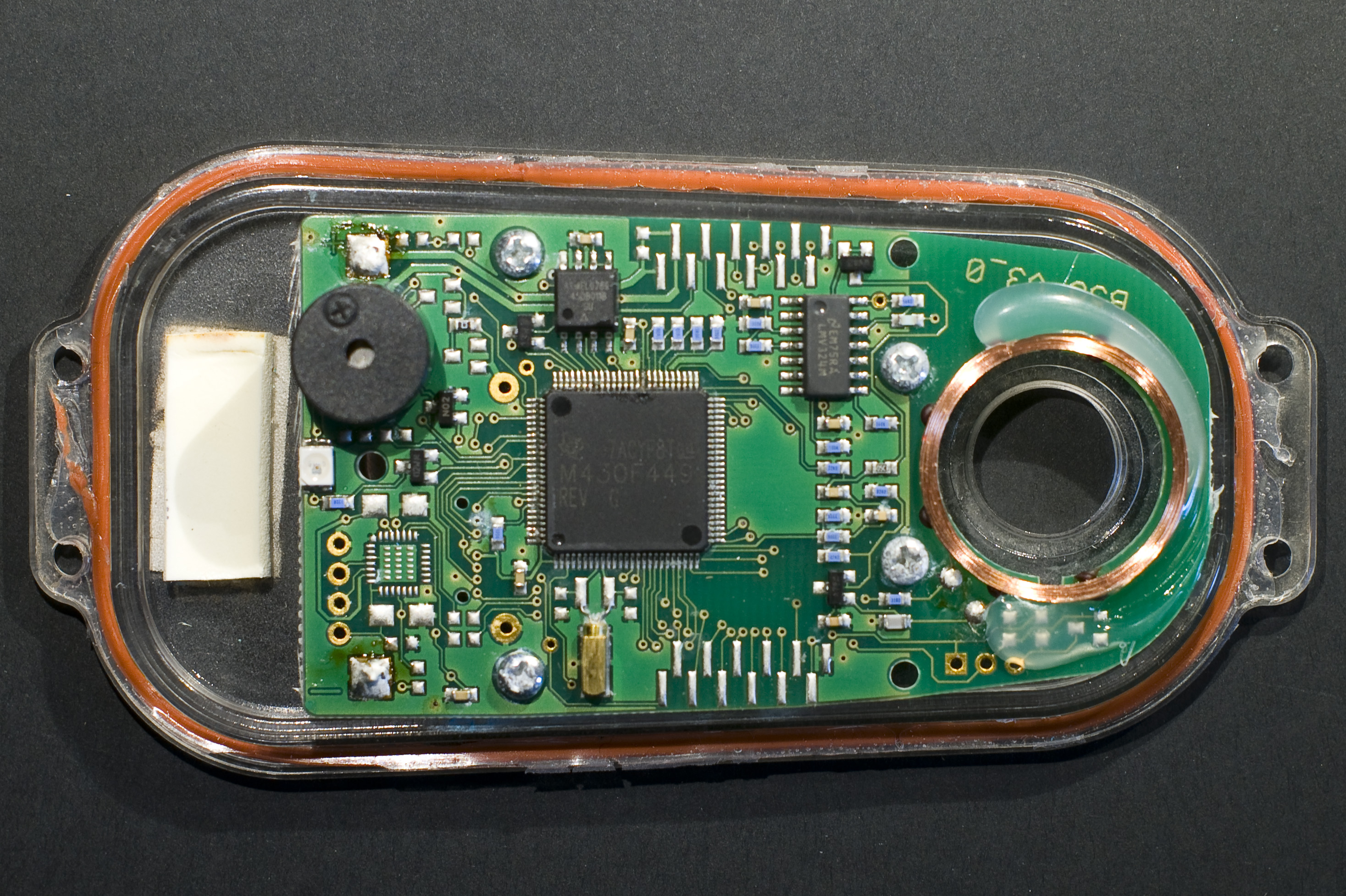
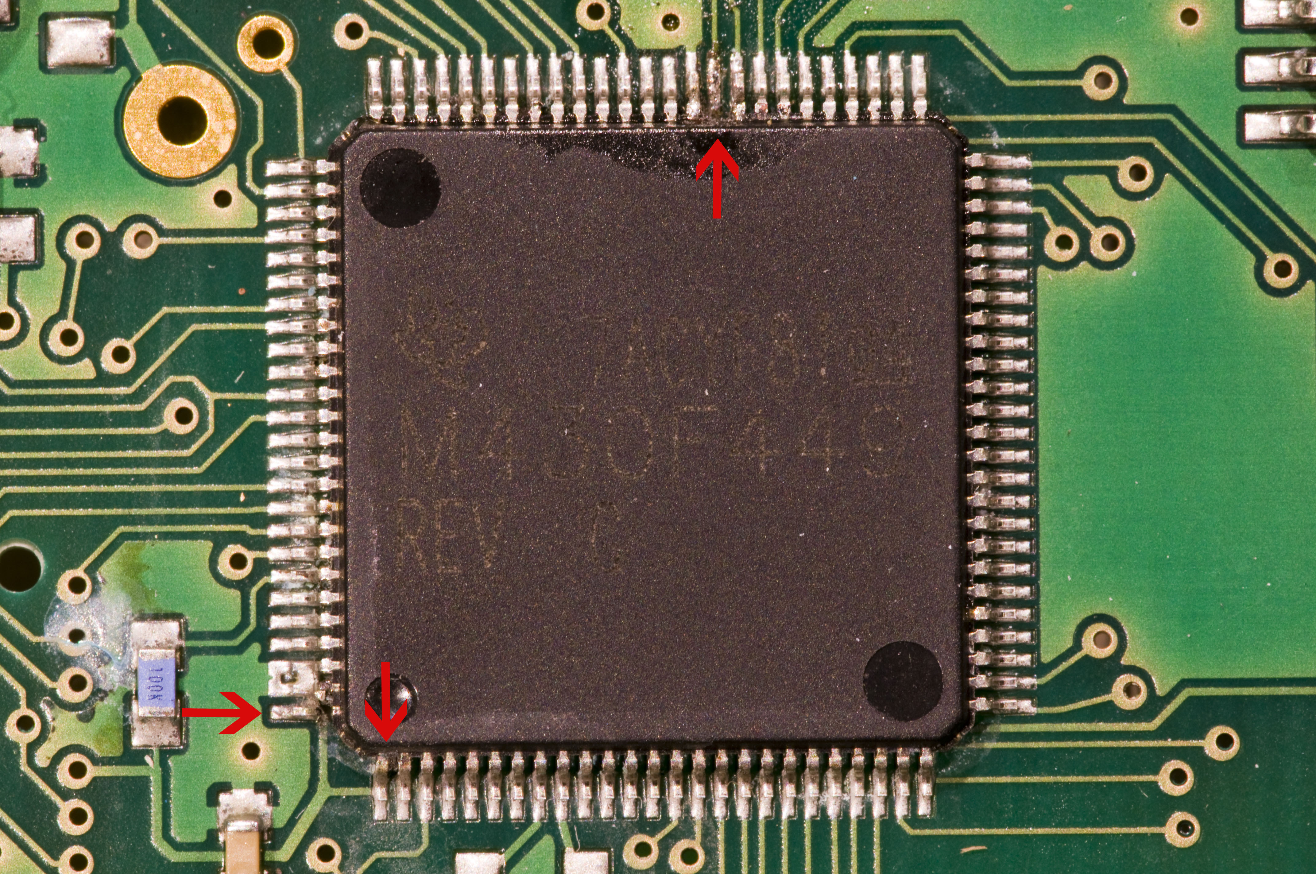
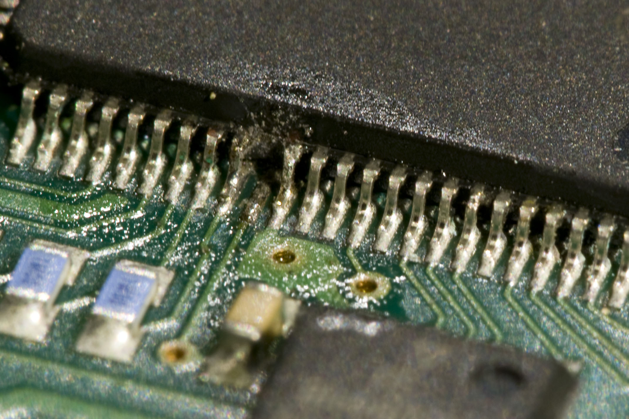
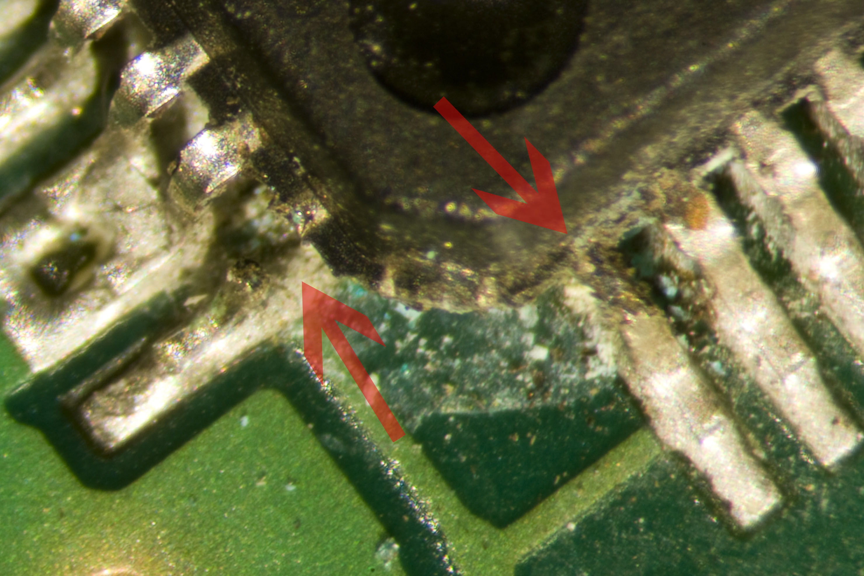
  • I looked around the PCB under a microscope and noticed something weird at pin 60 of the microcontroller. Closer inspection showed that the pin was more or less pulverized. The processor datasheet said that it was one of the power supply pins (DVCC2).
  • I tried to repair it, but it turned out that no metal of the pin was sticking out of the package anymore, so there was nothing to solder to.
  • I then noticed that pin 100, AVCC, was also broken and that while pin 1 (DVCC1) was still in one piece, it also seemed to have been damaged since it was thinner than the other pins.

My guess is that a huge amount of current has for some reason flown through the power pins such that they have melted (!). I am pretty sure I did not hook up the external power supply with the wrong polarity and anyway it was current limited to 100 mA or so, so I do not think I caused this by reverse power polarity. Could it be that the processor entered into some kind of state that effectively shorted its supplies and thus consumed a large current?

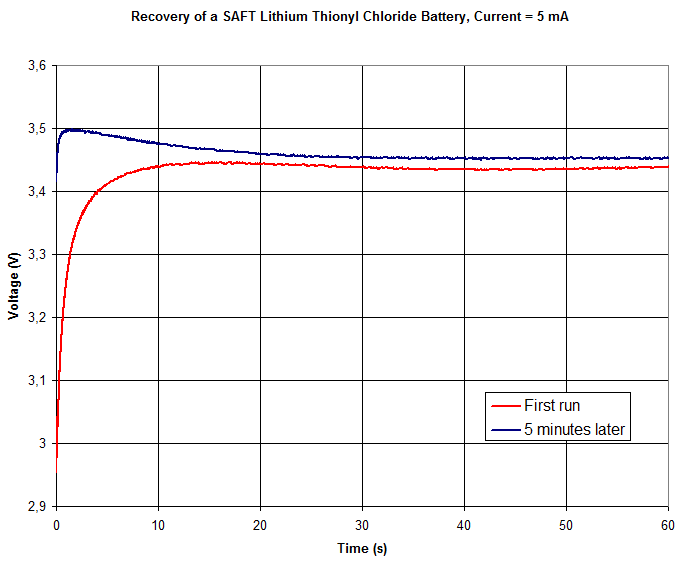
I guess the reason for the bug behavior in the release notes (a voltage reading of about 2 V) might be caused by an unexpected large current consumption, so it is somewhat consistent with power pins getting destroyed. But it seems a bit unlikely that the relatively wimpy lithium thionyl chloride battery could deliver enough current for this to happen. And I am almost certain that the damage to the pins occurred before I connected an external supply. Quite mysterious.

Update on 2015-07-26

After a discussion through a few emails back and forth with Simon Harston, we have come up with a new hypothesis that could explain the state of the station while not requiring an unrealistically large current that could melt IC pins:

  • For some reason (maybe a manufacturing defect), the battery released corrosive gas/fumes.
  • The corrosive environment  inside the station may have been exacerbated by moisture leaking in.
  • Corrosive and conductive films formed at a number of places inside the station, including around the MCU pins.
  • Leakage current flowed through the film, particularly from the MCU pins with the most positive potential (the VCC pins) to the neighboring GND pins.
  • This current effectively made the VCC pins behave as sacrificial anodes in an impressed current system for cathodic protection and thus made them deteriorate, while the GND pins were unaffected.

If this hypothesis is correct, it explains why just the VCC pins were destroyed. Furthermore, it does not require a current that is probably much higher than the battery could ever deliver. The bluish debris that can be seen in some of the photos (e.g. on the bottom side of the board and near the resistor close to pin 1 of the MCU) might have gotten its blue color from copper ions from the corroding pins, provided the ions could somehow migrate from the pins to the other locations. The fact that the screws are clearly corroded supports the hypothesis that there was a corrosive environment inside the station at some point.

(End of update.)

Below are some pictures of the unit. Unfortunately, I do not have a really good way of taking pictures through a microscope, so most pictures are taken through regular lenses and the one taken through the microscope is blurrier than one could hope for.
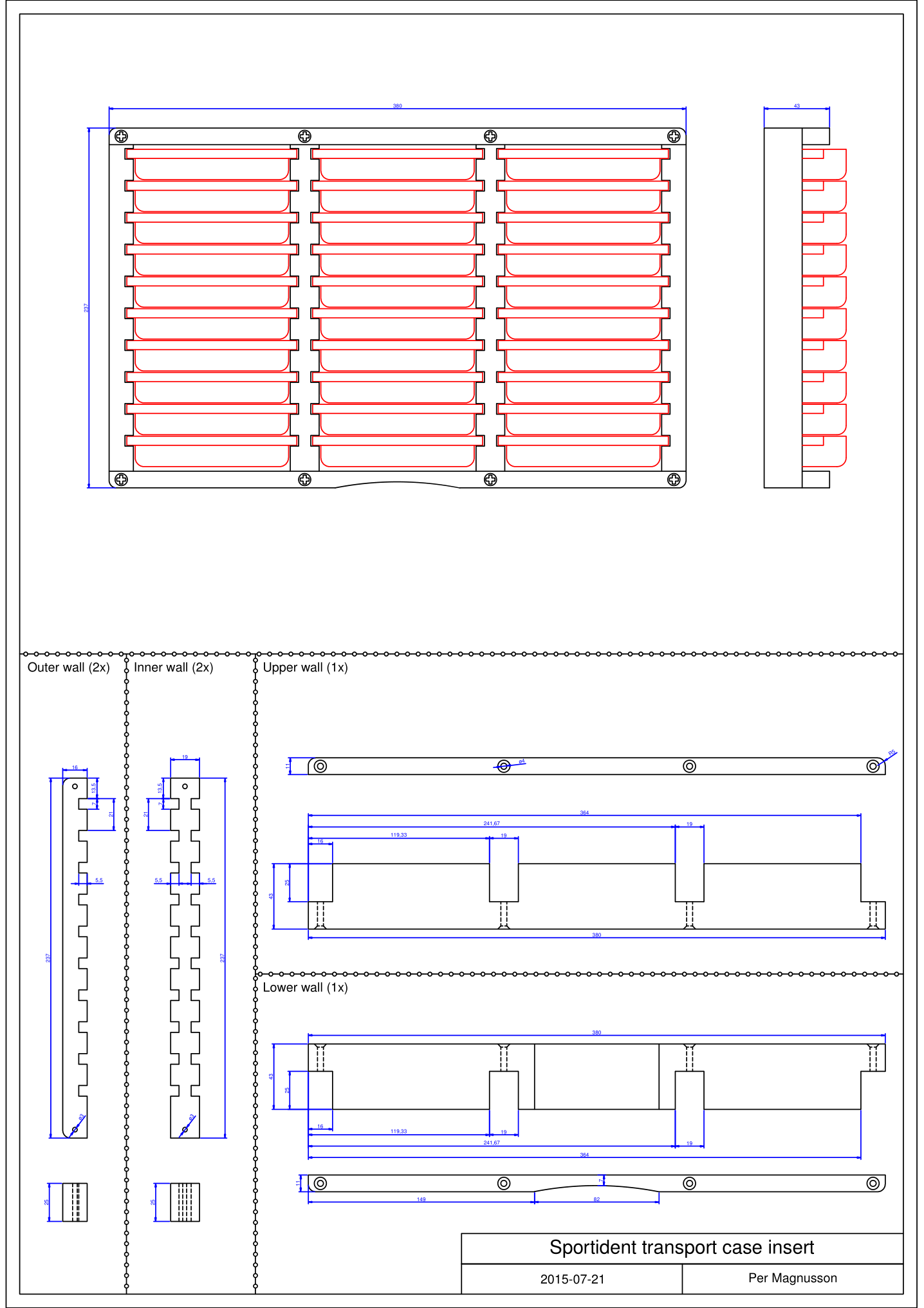
The broken SI station.
Top side of the PCB of the broken SI station.
Bottom side of the PCB of the SI station.
Bottom plastic cover with some mysterious blue material along the lower side.
The processor with arrows pointing to the damaged pins.
Closeup of pin 60 (after I desoldered the lower remains of the pin).
Pin 100 (AVCC) is broken.
Microscope photo of pins 100 (left) and 1 (right). Pin 1 is narrower than the other pins.
This battery with a cracked sleeve may have been in the faulty unit. I am not sure since I mixed up a number of discarded batteries.
This battery with a cracked sleeve may have been in the faulty unit. I am not sure since I mixed up six discarded batteries, two of which had cracked sleeves.

Sportident Transport Case Insert

To better organize Sportident control stations in their transport cases, I designed and built a couple of wooden case inserts. These inserts allow 30 stations to fit in one case while each station has a fixed position that can also be labeled. This makes it very easy to see if any station is missing and if so, which station has disappeared.

This is what the case insert looks like on its own and when fitted into a transport case and equipped with 30 base stations.

The case insert.
The case insert.
The case insert and 30 SI base stations.
The case insert fitted in a case and filled with 30 SI base stations.

I made a drawing with dimensions of the insert. It can be found below in PNG, PDF and DWG format.

SI case insert drawing (PNG format).

More On Voltage Delay in Lithium Thionyl Chloride Batteries

I found the three year old Tadiran batteries (TL-5101/P) that i described in the previous blog post to have too high internal resistance to be suitable for use in Sportident base stations. The datasheet of those batteries also only talk about a discharge current of up to 2 mA and the base stations use more than that for peak current. Therefore I ordered new batteries of another brand, namely SAFT LS14250 CNA. The datasheet of SAFT LS14250 recommends a maximum discharge current of 35 mA and it has near full capacity at 10 mA of current, so this seems like a much better choice for the application.

Naturally, I was curious as to what the voltage delay looked like for LS14250, so I hooked up my battery tester with the same software as before. I ran two tests on the same battery with about 5 minutes of delay in between. The plots below shows the results.

Voltage vs time during 60 s while loading the SAFT LS14250 battery with 5 mA.
Voltage vs time during 3 s while loading the SAFT LS14250 battery with 5 mA.

In the first run, which takes place presumably at least many days (perhaps months or years) since the battery was last delivering any current), we see the voltage under load starting out at about 2.95 V and it recovers to 3.45 V after about 15 s.

In the second runt, the initial voltage under load is above 3.4 V and it peaks at almost 3.5 V after 1.5 s. It then sags down a bit, but stays about 15 mV above the first trace between 20 and 60 s.

So the voltage delay phenomenon is (as expected) very evident also in this battery model. Also, the SAFT LS14250 seems to be much more suited for the application than the Tadiran TL-5101/P.

Update on 2015-07-11:

I also needed to change batteries on some SI master (BSM7) units and these have AA-size (14500) batteries with higher capacity than the 1/2 AA size 14250 discussed above. I tested a new SAFT 14500 battery (which has  a highest recommended discharge current of 50 mA) twice with the 5 mA one-minute test. The results are shown in the plot below.

Voltage vs time during 60 s while loading the SAFT LS14500 battery with 5 mA.

The voltage delay effect is evident also in this test, but strangely enough the curves look qualitatively different compared to the LS14250 curves. In the first run, the voltage dips during the first second before it starts to recover and reaches a peak after about 25 seconds followed by a slow decay. The initial dip is a new feature.

The second test of the same battery, ten minutes later, shows a quick recovery that peaks after three seconds after which the voltage slowly decays. After about 15 seconds, the voltage dips below that of the first run, unlike what happened when testing the LS14250 battery in which case the voltage during the second run stayed above that of the first run for the full minute.

The intricacies of battery behavior are apparently complicated, but tentatively one can conclude that a “voltage delay” effect that takes place for 1-15 seconds when the battery is being loaded after a (long) time of storage is repeatable based on the findings of these few tests.