I am prototyping a wireless sensor node based on a (cheap) FRDM-KL25Z board from Freescale containing an ARM Cortex-M0+ processor and a (not quite as cheap) XBee ZigBee module from Digi. This blog post briefly describes the first steps of the prototyping, namely to get to the point where the XBee is connected to the FRDM board and they talk to each other.
I decided to use the mbed environment to develop the program and in order to do that, I had to change the FRDM board firmware according to these instructions.
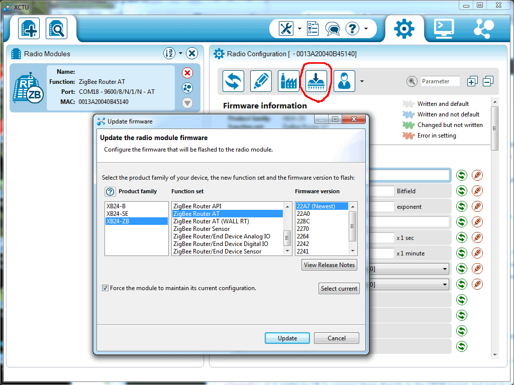
For the initial tests, I wanted to write AT commands to the XBee from a terminal on the PC via the FRDM board. The XBee can run any of a number of different firmwares and in order for it to understand AT commands, one of the AT firmwares need to be loaded. This is done using the XCTU program from Digi while the module is connected to a PC serial port, e.g. through the SparkFun XBee Explorer USB board. Below is a screenshot from XCTU showing the major steps to program an AT firmware into the XBee module.
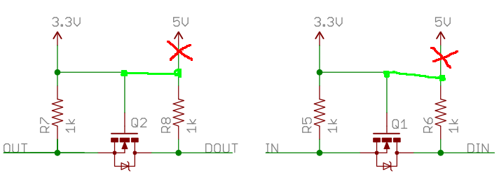
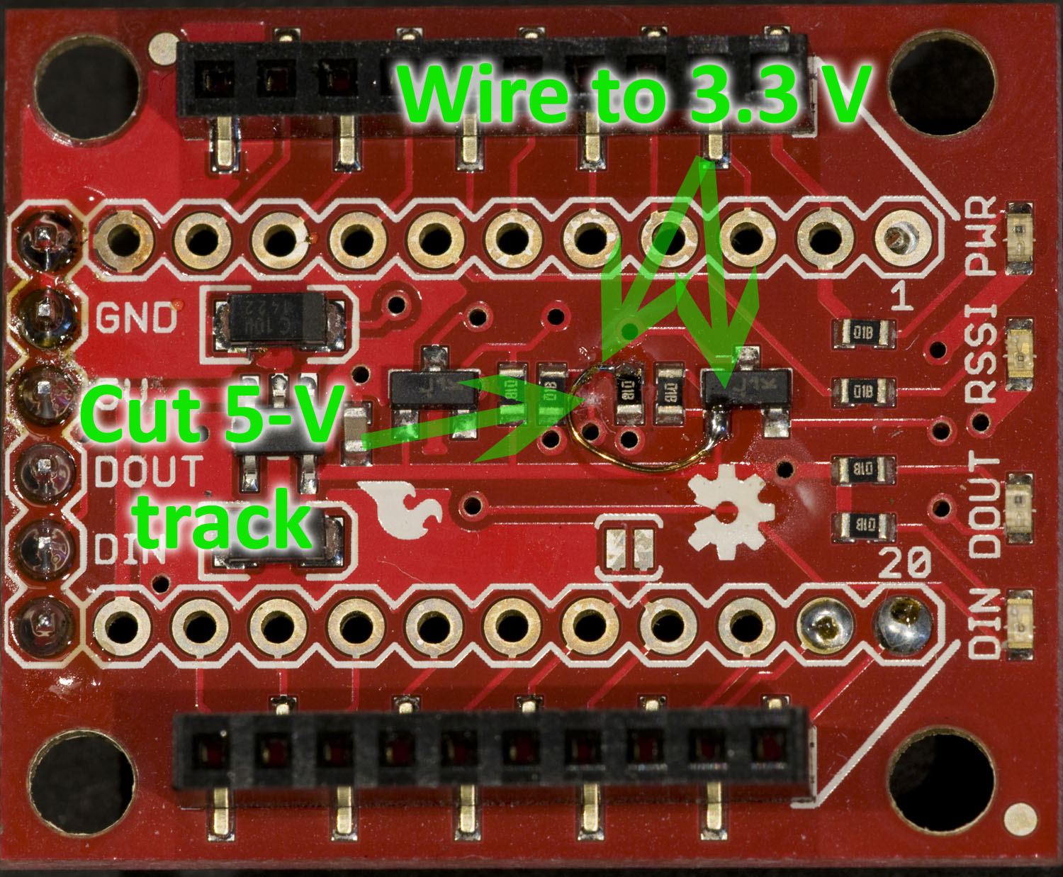
The XBee module interface is a 3.3 V serial port running at 9600 baud, and the Cortex-M0+ processor also runs at 3.3 V, so this should match nicely. However, I have the XBee mounted on a Sparkfun XBee Explorer board, which translates the 3.3 V serial port to 5 V levels. The translation is done via pass transistors and pull-up resistors (see the schematic), so it might be OK to connect them directly to the FRDM board, but just to play extra nice with the FRDM board I decided to mod the XBee explorer so that the pull-ups go to the 3.3 V supply instead of the to 5 V supply as shown in the schematic excerpt and the photo below:
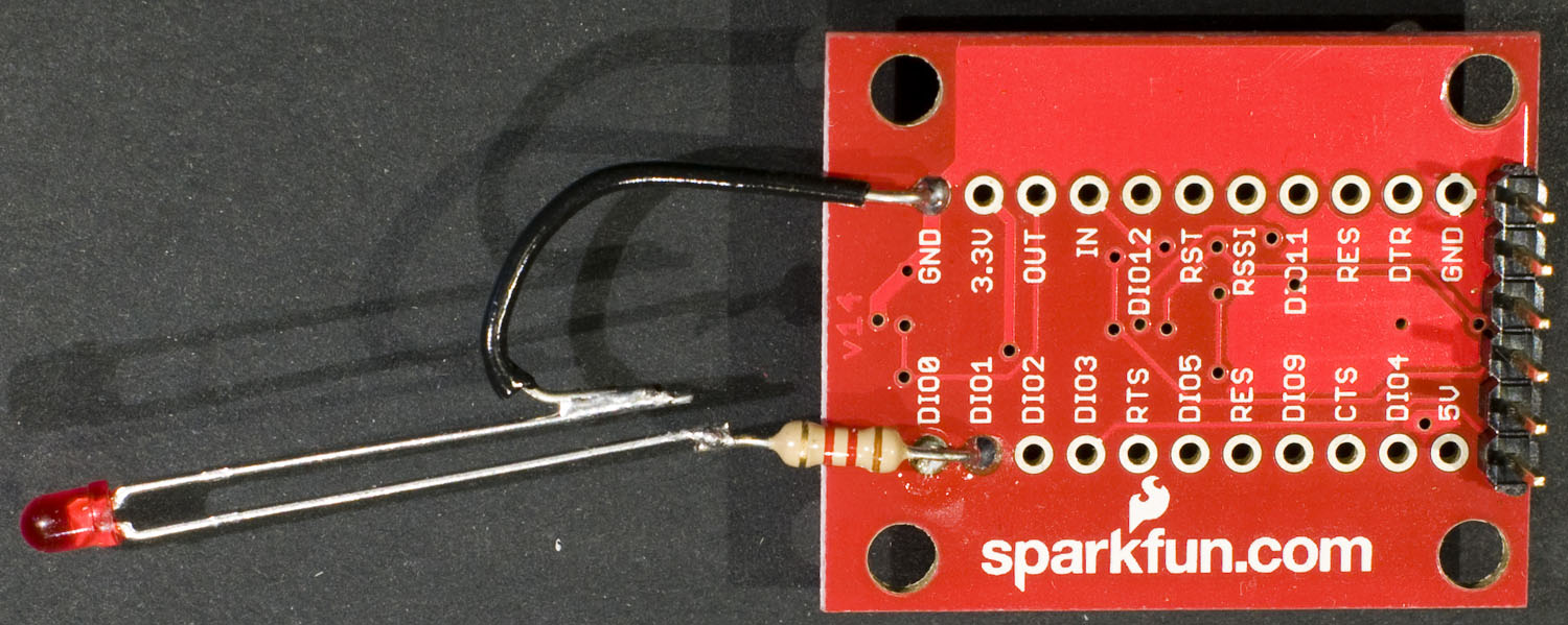
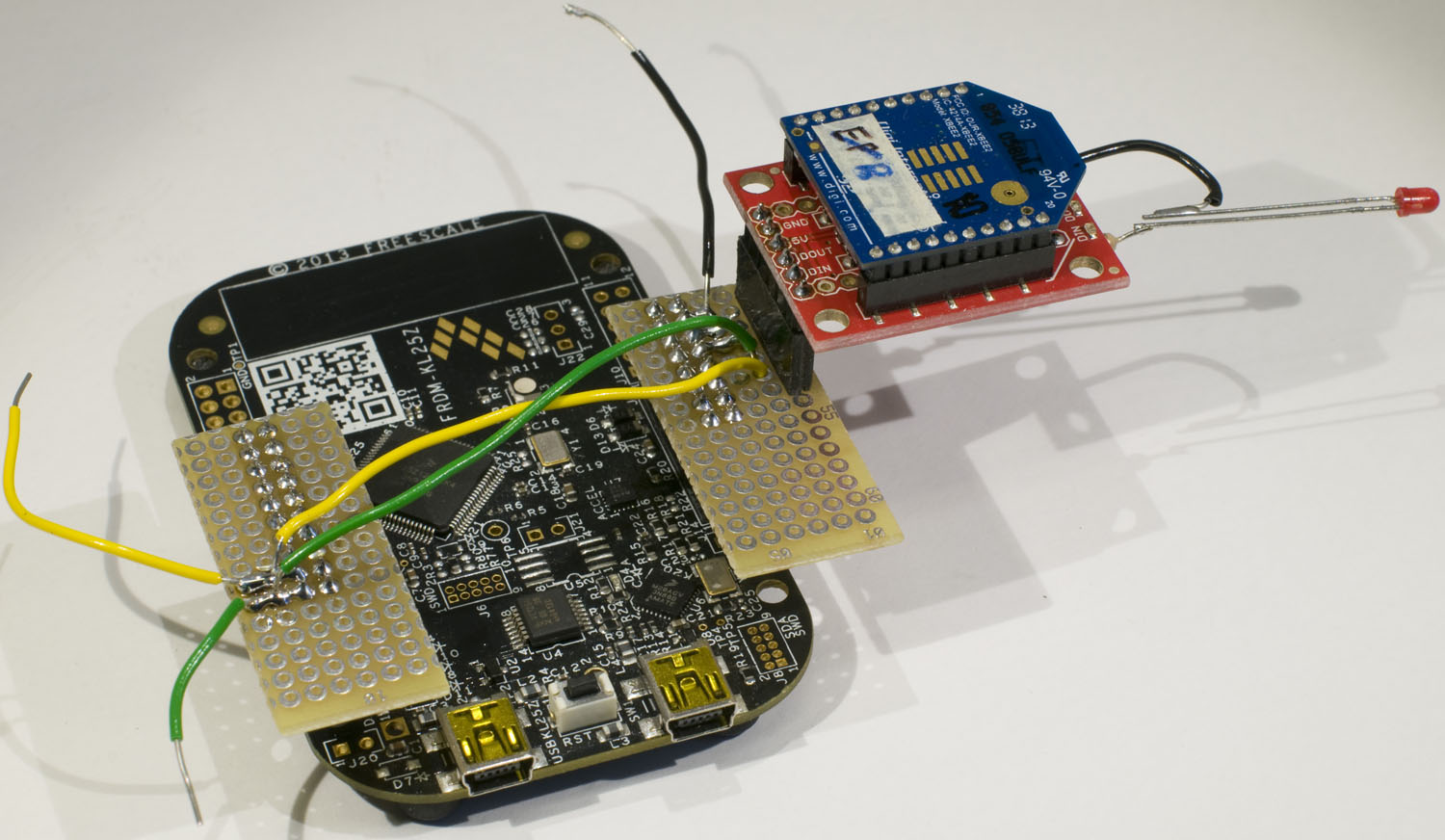
One easy way of physically getting a confirmation of successful communication with the XBee (apart from serial port responses to the AT commands) is to connect an LED to one of the digital I/O-pins. Below is a photo of how I connected an LED to XBee I/O-pin 1.
Now we need to connect the XBee to the FRDM board. There are several pins that can be used as serial I/Os on FRDM-KL25Z and based on the schematics, I happened to select PTE0 (also known as D14 and J2 pin 18) for UART1_TX and PTE1 (also known as D15 and J2 pin 20) for UART1_RX. This pin pair can also used for I2C bus 1, but if I later need to use that bus, I can route it out on PTC10 and PTC11, or I can use different pins for the UART. This page has a picture that may serve as a guide for pin selection. GND and 5V to supply the XBee is available on pins 10 and 12 respectively in the connector J9.
If I had used the simpler breakout board instead of the one with a regulator and level translation, I would not have needed the level translation patch and I would have used the 3.3 V supply from the FRDM board instead of the 5 V supply.
I soldered sockets to the FRDM board connectors J2 and J9 and pin headers to small pieces of prototype board. In one of these I placed a header for the XBee breakout board and then I connected 5V, GND, RX and TX. The whole thing may not be particularly mechanically robust, but it serves its purpose, see photo below.
A program for the FRDM board is of course needed as well. I made it very simple; characters coming from the serial port from the PC are sent on to the XBee and vice versa. Also, characters from the PC are echoed back to the PC. I also flash the RGB LED based on what is happening as further feedback. Here is the code:
#include "mbed.h"

Serial pc(USBTX, USBRX);
Serial xbee(PTE0, PTE1);
DigitalOut redled(LED1);
DigitalOut greenled(LED2);
DigitalOut blueled(LED3);

int main() {
    char bufchar;

    blueled = 0; // Turn blue led on
    pc.printf("Type what you want to transmit to the XBee.\n\r");
    xbee.baud(9600);
    greenled = 1; // Turn green led off
    redled = 1; // Turn red led off
    blueled = 1; // Turn blue led off
    while (1) {
        if (pc.readable()) {
            greenled = 0;
            bufchar = pc.getc();
            xbee.putc(bufchar);
            pc.putc(bufchar); // Local echo
            greenled = 1;
        }
        if (xbee.readable()) {
            redled = 0;
            bufchar = xbee.getc();
            pc.putc(bufchar);
            redled = 1;
        }
    }
}
To be able to talk to the FRDM board as a USB serial port, a Windows driver is needed. This can be found on the mbed site. As a serial terminal program, I decided to use Tera Term, which is free. I set it up for communication at 9600 bauds with the serial port number that Windows assigned to the FRDM board serial port.
To get into AT command mode in the XBee module, three plus signs (+) must be sent guarded by at least a 1 second pause before and after. The module returns to transparent mode 10 seconds after the last activity on the serial port, so an AT command have to be sent within this time. To test the LED I connected to the XBee module, I use the command ATD14 (set XBee IO pin 1 low) and ATD15 (set XBee IO pin 1 high). For some reason these commands do not take effect until the module reverts to transparent mode, and in order to not have to wait the 10 seconds for a timeout, I issue the ATCN command, which forces the module to immediately go to transparent mode so that the LED update happens. I am not sure it is meant to work this way.
Below is a screenshot of the terminal window showing the commands and the response from the system.
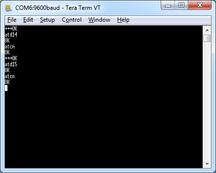
The OK texts come from the XBee module.
So far so good. For the sensor application, I will not use AT commands, but instead use the API mode, but this exercise served as a stepping stone that allowed verification of the connection between the processor board and the XBee module.
2 thoughts on “Interfacing an XBee Module to a FRDM Board”