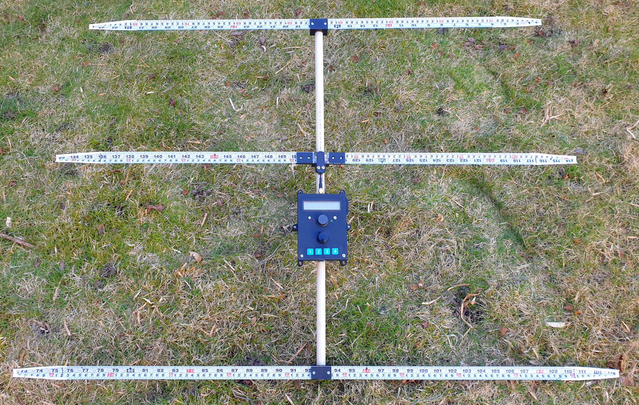
This article describes a Yagi antenna I have designed for use in a “fox hunting” receiver for the 2 m band (144 MHz). The antenna uses 25 mm wide steel tape measure for the elements, 16 mm PVC pipe as the boom and 3D-printed parts to keep it all together. Models for the 3D-printed parts are available for download.
Link to a zip-file with 3MF models of the parts:
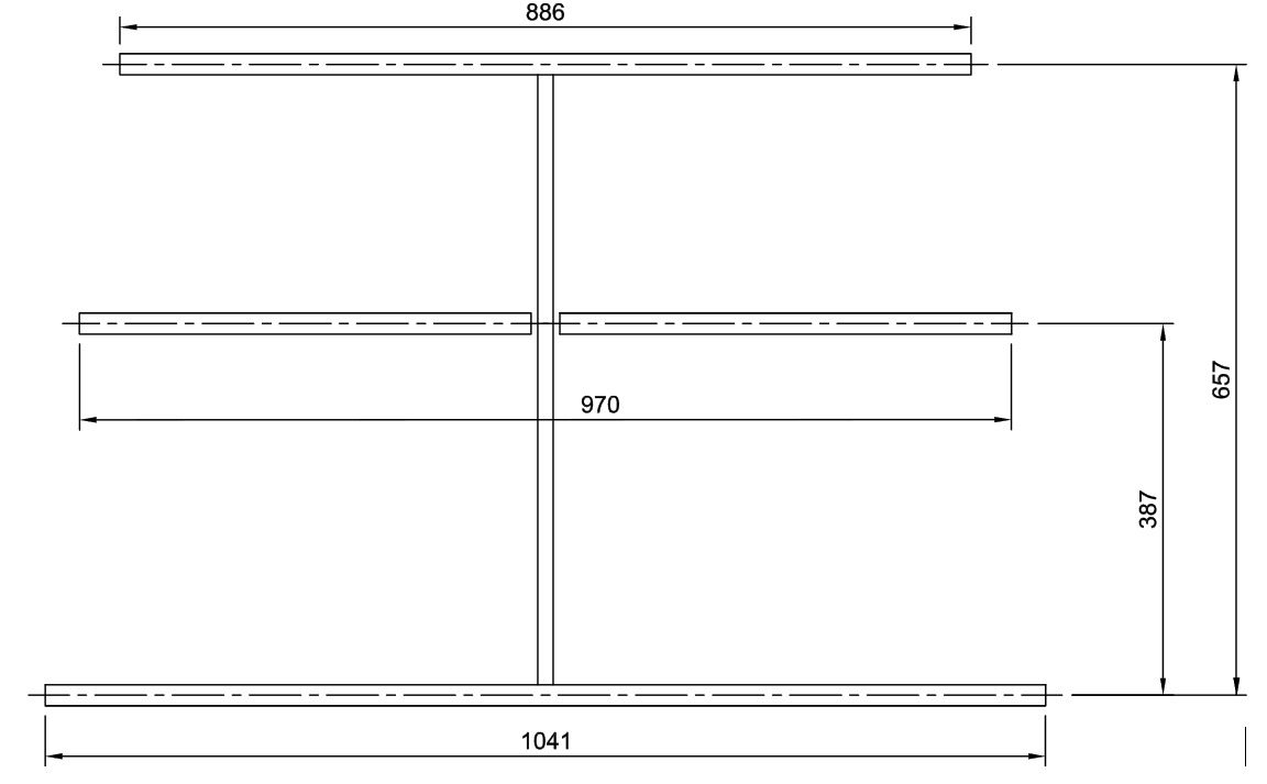
Several Yagi antenna designs for the sport of fox hunting (or ARDF, amateur radio direction finding) have been published and can be found by some searching on the web. I decided to have a go at designing such an antenna myself and used the free YagiCAD program to do so. After a number of rounds of optimization starting from different base designs, I ended up with the following:
Antenna dimensions [mm]
The shortest element is the director (towards antenna main lobe) while the longest is the reflector. The “driven” element is the one in the middle.
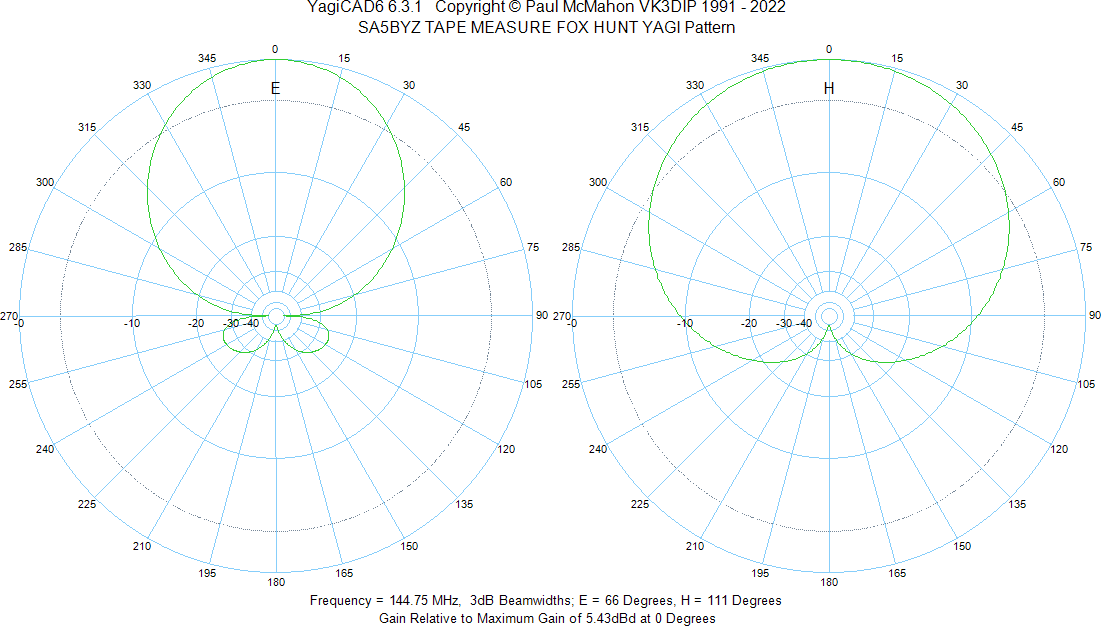
According to YagiCAD, the radiation pattern of the antenna is as follows:
Simulated antenna radiation patterns at 144.75 MHz
Front-to-back ratio is simulated to be above 40 dB.
While I have not measured the real antenna diagram, the subjective assessment is that the antenna performs well. Using a network analyzer, I have found that it’s impedance is around 40 -j0 ohms at 145 MHz.
For the beam, I used a piece of 16 mm outside diameter PVC electrical conduit pipe (“VP-rör” in Swedish).
For the elements, I used 25 mm wide steel tape measure from Biltema, e.g. part number 16-2931.
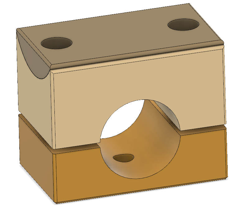
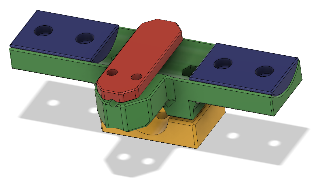
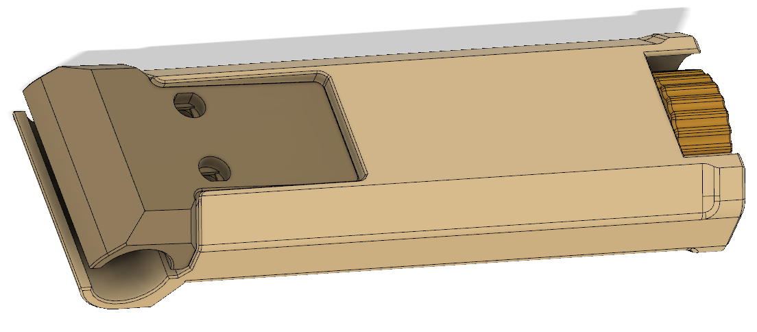
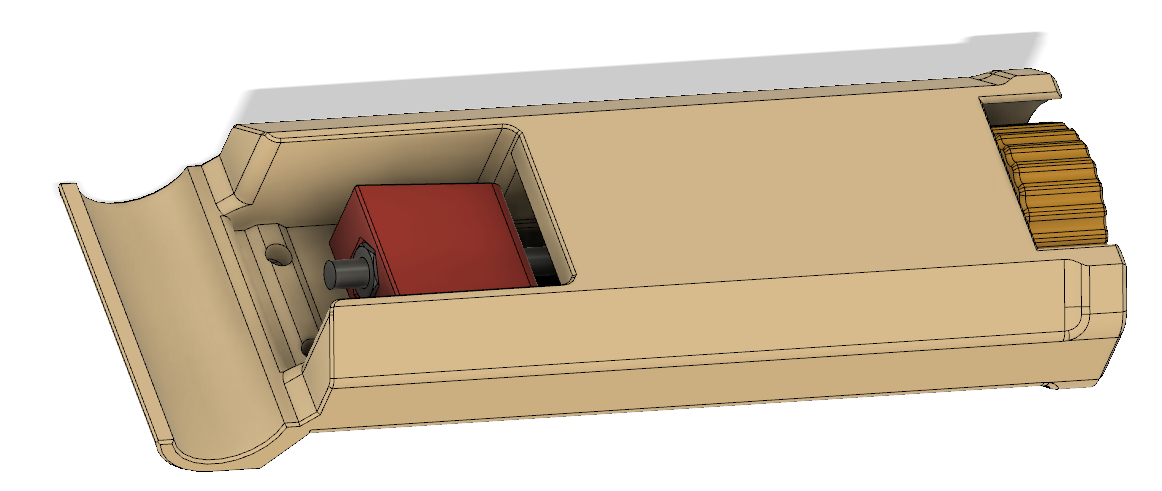
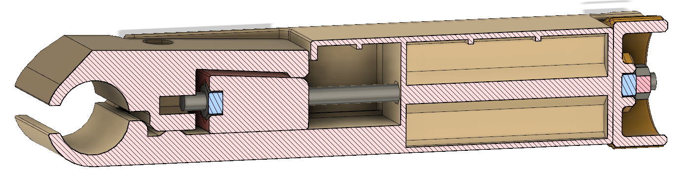
To mechanically connect the elements to the beam, I designed various clamps that I printed on my 3D printer. The antenna needs to be made smaller for storage and transportation, so I also designed spools and clamps to allow the elements to be rolled up and kept securely in that state. Furthermore, I have designed a handle that can grip on the pipe and be secured by a screw pulling a wedge. Pictures of all these parts are shown below.
Clamp for director and reflector. Requires M3 screws and nuts.Clamp for driven element, including a strain relief (red) for an RG174 coax and some sideways adjustability of the elements for tuning. Requires a few M3 screws and nuts.Another view of the clamp for the driven element. Note the slots in the green part that allows the length of the elements to be adjusted by a few mm.Spool for rolling up an antenna element. The spool consists of two halves that need to be glued together, a 5 mm long M2.5 screw and a removable center pin that helps while rolling up the element. One pin can be used for all six spools.Antenna spool with a clamp (red) that secures the rolled-up tape measure (not shown). Note the peg on the red clamp that fits in one of the notches on the spool (to the right in this picture) to prevent the whole thing from unrolling.One half of the spool. There are three holes where short pieces of filament can be inserted to help with alignment during glue-up and to make the glue-up stronger.The end of each antenna element needs to be chamfered at a shallow angle and a 3 mm hole has to be made to fit in the M2.5 “hook” inside the spool. The sharp cut edges can be made less dangerous by putting sports tape over them.Complete handleHandle without the clamp, showing the wedge and screw.Cross section of handle, showing the wedge, screw and knob that pulls on the wedge to secure the grip on the pipe.Complete receiverReceiver ready for storage or transportation with rolled-up elements and the handle folded to the sideClose-up of antenna elements rolled-up on spools with clamps holding them in place
Det här blogginlägget är andra och avslutande delen i en artikelserie där jag beskriver en mottagare (“rävsax”) för radiopejlorientering på 80m-bandet. En snarlik variant av artikeln publicerades i Sveriges Sändaramatörers, SSA:s, tidskrift QTC i nummer 10 och 11, 2022.
Denna andra del beskriver elektroniken, mekaniken och mjukvaran.
Blockschema
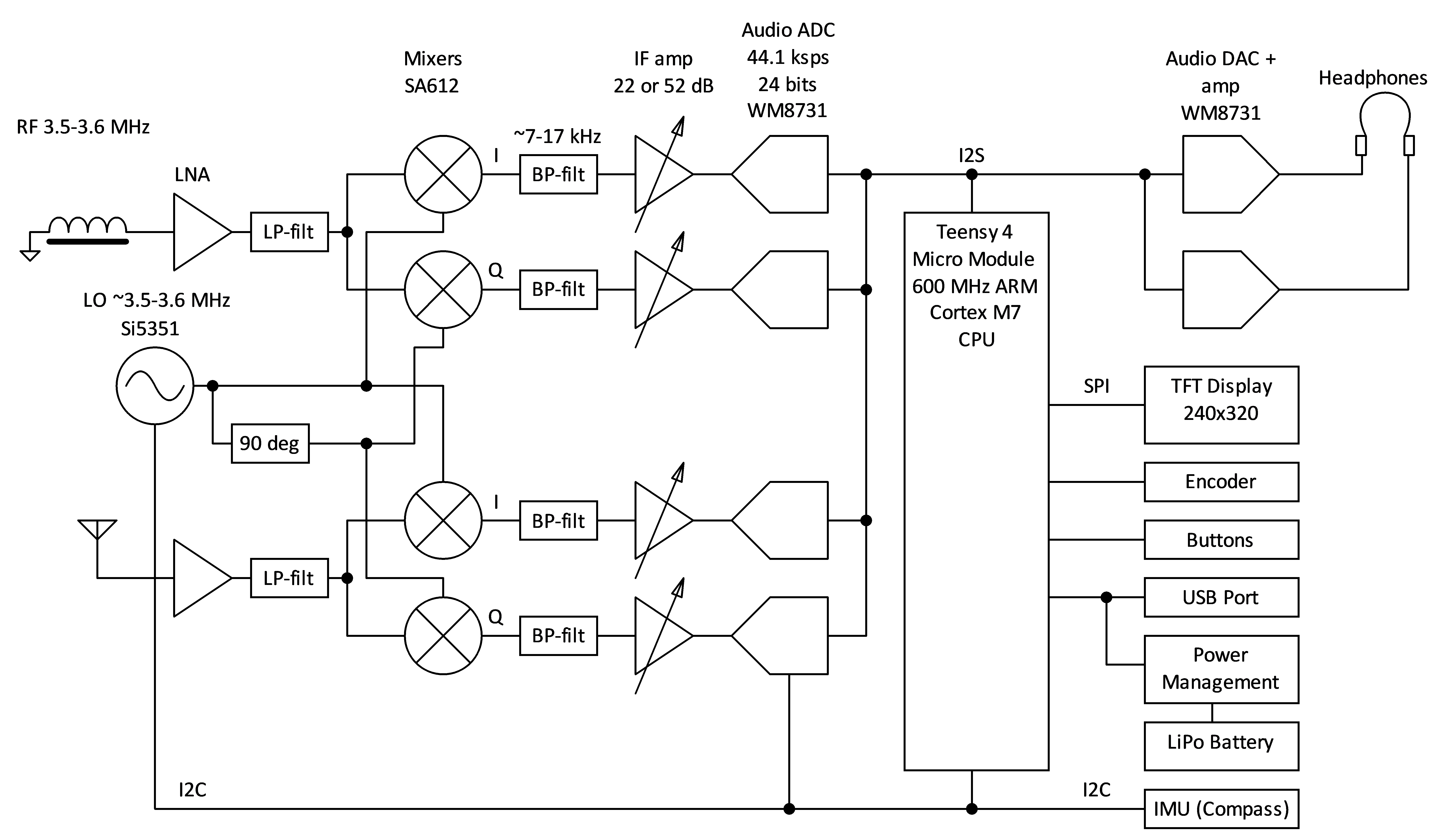
Figur 16 visar ett blockschema över mottagaren. Utöver vad som framgår av denna bild så händer en hel del intressanta saker i mjukvaran i processorn. Mer om det senare.
Figur 16. Blockschema
Som synes finns det två identiska mottagarkedjor, en för H-fältet och en för E-fältet. Antennsignalerna förstärks något av lågbrusförstärkare (LNA), filtreras och mixas med två lokaloscillatorsignaler som är fasvridna 90 grader från varandra. Detta möjliggör att man senare undertrycker det oönskade sidbandet.
Efter nedmixning till nära basband (nominellt 13 kHz) så bandpassfiltreras signalerna och förstärks med antingen 22 eller 52 dB innan de digitaliseras av 24-bitars audio codecs i en takt av 44.1 kHz. Inbyggt i AD-omvandlarna finns mycket effektiva antivikningsfilter med minst 60 dB dämpning från halva samplingsfrekvensen upp till åtminstone tredubbla samplingsfrekvensen. En tämligen kraftfull mikro-controller i form av en i.MX RT1062 från NXP sköter sedan resten av signalbehandlingen samt användargränssnittet i form av en grafisk display, en ratt och några knappar. Den färdigbehandlade signalen skickas till audio-DAC:ar med inbyggda hörlursförstärkare. För tillfället skickas samma signal till både höger och vänster kanal, men man skulle kunna tänka sig någon annan lösning i framtiden.
Konstruktionen innehåller även ett LiPo-batteri med laddarkrets, en USB-kontakt för laddning och programmering och en IMU, inertial measurement unit, som består av en magnetometer, en accelerometer och ett gyro för att kunna avgöra i vilken kompassriktning som antennen för tillfället pekar.
Processorn
Processorn sitter på en liten s.k. Micro Module som görs av SparkFun [3]. Genom att använda en färdig modul istället för att sätta processorn och tillhörande komponenter direkt på kortet slipper man dels löda en ganska besvärlig 196-bollars BGA-kapsel och dels får man på köpet en trevlig boot loader som gör att man enkelt kan programmera den via en USB-kabel. Det visade sig också lättare att få tag på denna modul än att köpa en lämplig lös processor i den bedrövliga halvledarbrist som råder. Modulen ansluts i en liten ytmonterad kontakt liknande de som används för moderna solid-state-diskar i M.2-format. Kontakten har 67 anslutningar fördelade på två rader med 0,5 mm centrumavstånd mellan benen och modulen är ca 22×22 mm, vilket gör det hela till en kompakt lösning.
i.MX RT1062 är en 32-bitars ARM Cortex-M7-processor som kan klockas i upp till 600 MHz, har stöd för flyttal och massor av periferienheter, såsom interface för I2S, I2C, SPI samt DMA, realtidsklocka, timers mm. Den har också mycket minne för att vara en mikrocontroller; 1 MB RAM och 16 MB flash finns på MicroMod-kortet. Att processorn är så kraftfull gör att programutvecklingen blir mycket enklare än om man ständigt behöver optimera och kompromissa med varje liten funktion man lägger till. Det finns också gott om färdiga programpaket, både från PJRC som utvecklar Teensy-familjen, från Arduino-världen, från ARM och från alla möjliga andra utvecklare och företag som släpper öppen källkod på t.ex. GitHub.
Elektroniken
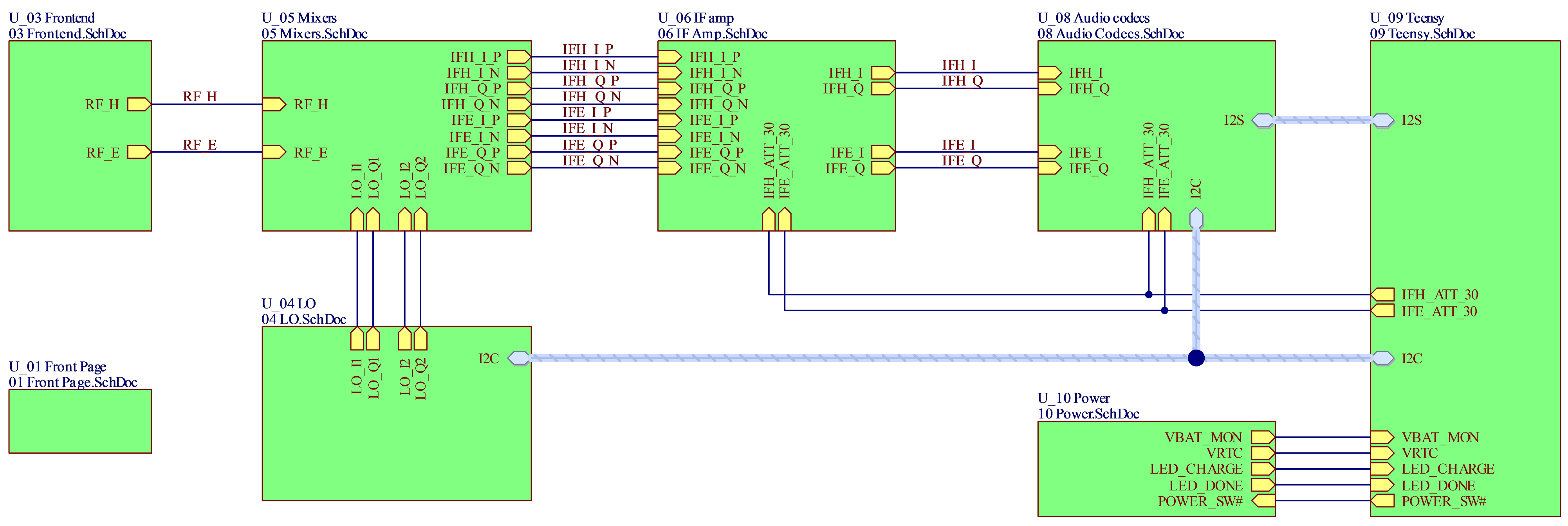
Kopplingsschemat är uppdelat på flera olika sidor. Figur 17 visar hur de hänger ihop med ett grönt block per schemasida.
Figur 17. Sammankopplingen av de olika schemasidorna. Signalflödet är huvudsakligen från vänster till höger.
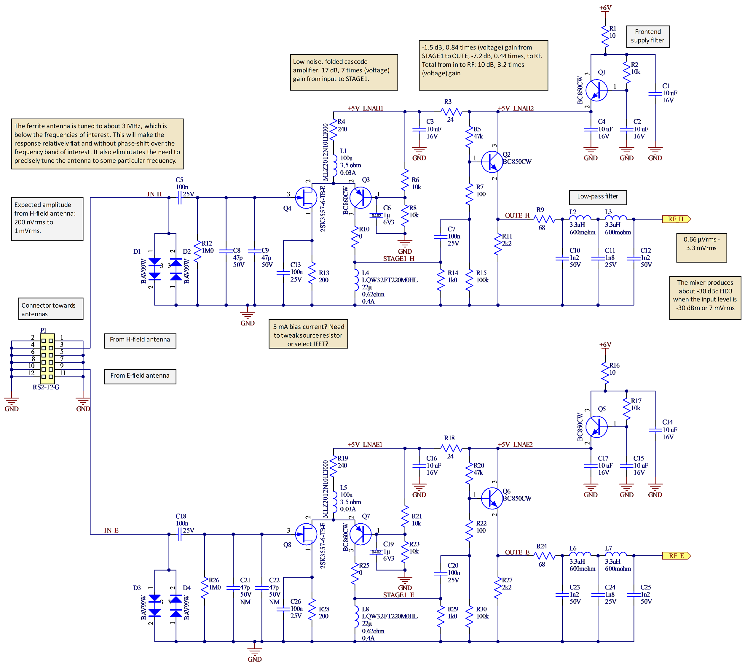
I figur 18 visas de två identiska lågbrusförstärkarna som buffrar, förstärker och filtrerar signalerna från de två antennerna. Jag beskriver här den övre kretsen.
Figur 18. De två lågbrusförstärkarna.
P1 är en hylslist för anslutning mot antennerna där de flesta benen är skärmande jord. D1 och D2 skyddar mot överspänningar och ESD. Genom att ha två dioder i serie blir kapacitansen mindre och påverkan på antennens resonansfrekvens inte lika stor. C8 och C9 monteras inte (gäller alla komponenter märkta ”NM”, Not Mounted). Q4, 2SK3557-6, är en JFET med lågt brus och hög inimpedans. När jag letade lämpliga lågbrusiga FET:ar att använda i denna position tyckte jag det här såg ut att vara bästa alternativet, även om det inte finns tydliga data för bruset vid 3,5 MHz i databladet. Förhoppningsvis är spicemodellen inte alltför missvisande. J310 brukar annars vara ett populärt val i sådana här sammanhang, men den ser ut att vara brusigare. Jag har inte gjort några systematiska mätningar för att försöka ta reda på verkliga brusprestanda, men jag har gjort väldigt många simuleringar i den kraftfulla gratissimulatorn LTSpice.
Q4 utgör tillsammans med Q3 ett folded-cascode-steg. Basen på Q3 är RF-jordad och därmed är även emitterspänningen (nästan) konstant, vilket gör att man inte får någon millereffekt som ökar ingångskapacitansen hos Q4. Genom att Q3 sitter ”bredvid” Q4 och inte ovanför som i en vanlig cascode så behöver man inte lika hög matningsspänning. Priset man betalar är att de två transistorerna behöver separata biasströmmar, vilket ökar strömförbrukningen.
R4 och L1 fungerar som strömkälla till cascodesteget. Utan L1 hade brus från R4 signifikant bidragit till förstärkarens brus och med enbart L1, men utan R4, hade biasströmmen blivit väldigt känslig för temperatur och komponenttoleranser. När Q4 vill ha mycket ström (positiv amplitud från antennen) blir det mindre över till Q3 och vice versa, så i princip flyter lika mycket signalström genom Q4 som ut från kollektorn på Q3, om än med omvänd fas.
L4/R14 utgör last till första förstärkarsteget. R14 såg inte ut att behövas i simuleringar, men i praktiken var det bra att ha för att undvika resonansproblem. Brusbidraget från R14 är tämligen begränsat. Även R7 har som syfte att minska risken för självsvängning.
Q2 är en emitterföljare som buffrar den högimpediva utgången från cascodesteget för att kunna driva ett lågpassfilter med 75 ohms impedans (mer lättdrivet/strömsnålt än 50 ohm och det finns inget i den här delen av kretsen som tvingar fram användandet av just 50 ohms impedans) och sedan mixrarna.
Spänningsförstärkningen (det är svårt att tala om effekt här eftersom impedanserna på många ställen inte är väldefinierade) är ca 7 gånger från gaten på Q4 till kollektorn på Q3 och efter dämpningen som orsakas av främst den impedansanpassande R9 så är den nere på totalt ca 3,2 gånger vid filtrets utgång.
Enligt simuleringar med en modell av ferritantennen som är resonant under 3 MHz så är det brus från J1 som dominerar vid 3,5 MHz (vid antennens resonansfrekvens är det lustigt nog istället förluster i antennen som dominerar, följt av brus från Q3).
Q1 filtrerar matningsspänningen för att undvika att störningar kommer in den vägen. En något enklare variant av detta matningsfilter används på flera ställen i [4]. R3/C3 ger ytterligare filtrering av matningen till ingångssteget.
Figur 19 visar de fyra balanserade mixrarna.
Figur 19. Schema för mixrarna.
Som mixrar används de klassiska SA612 av gilbertcelltyp. Det finns två par av mixrar, ett för H-mottagaren och ett för E-mottagaren för att skapa I- (in phase) och Q- (quadrature phase) versioner av de nedblandade signalerna. Här beskrivs bara H-mottagaren (övre delen av figur 19).
Eftersom mixrarna dels har en ganska hög inimpedans på minst 1.5 kohm och dels är balanserade passade jag på att använda 4:1-transformatorer mellan ingångsförstärkarna och mixrarna. De höjer impedansen från 75 ohm till 300 ohm och gör samtidigt signalen differentiell och med dubbla spänningsamplituden. R80 tillsammans med mixrarnas inimpedans terminerar signalen och ser därmed till att det föregående filtret jobbar i önskad impedans. Det går att driva mixrarna single-ended (så som i 80m12), men signalkvaliteten blir rimligen bättre om man driver dem differentiellt.
Den föregående förstärkningen ser till att bruset från mixrarna (brustal ca 5 dB) inte dominerar. Man vill såklart att första förstärkarsteget, där signalerna med nödvändighet är svagast, ska dominera bruset.
Utsignalen från mixrarna är också differentiella och det utnyttjas för bästa signalkvalitet i de följande MF-förstärkarna på bekostnad av en del komplexitet. De aktiva mixrarna förstärker för övrigt signalen 5–7 gånger. Frekvensen hos MF-signalen är nominellt 13 kHz. Ytterligare nedblandning till under 1 kHz sker senare i mjukvara.
Kondensatorerna C58 etc. tvärs över utgångarna på mixrarna bidrar till lågpassfiltrering tillsammans med utimpedansen på ca 1,5 kohm.
LO-signalerna i fas och kvadratur skapas på en annan schemasida, se längre ned i artikeln, och termineras av 75-ohmsmotstånd vid mixrarna.
Q11 filtrerar matningsspänningen på samma sätt som Q1 gör vid ingångsförstärkaren.
De fyra mixrarnas utsignaler går till varsin MF-förstärkare. Se figur 20 och 21.
Figur 20. MF-förstärkarna. Innehållet i de fyra blocken framgår av nästa figur.
Q14 skapar en lämplig nivå på den förstärkningskontrollerande signalen. Q13 filtrerar matningen till förstärkarna. U12 skapar en ganska lågimpediv flytande ”jord” på halva förstärkarnas matningsspänning.
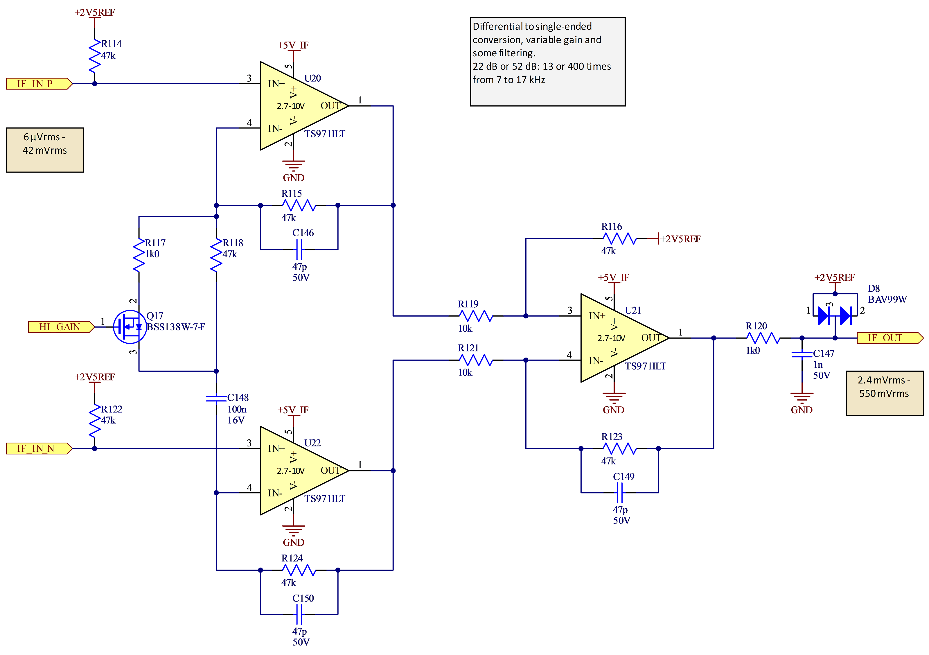
Figur 21. Schemat för var och en av MF-förstärkarna.
Varje MF-förstärkare har flera uppgifter:
att konvertera den differentiella signalen från mixrarna till en single-ended signal
att bandpassfiltrera signalen
att kunna förstärka antingen lite (13 gånger) eller mycket (400 gånger) beroende på hur stark signalen är.
Detta åstadkoms med en instrumentförstärkarkoppling med tre operationsförstärkare (opampar) av typ TS971. Valet av dessa beror på att de dels var tillgängliga (ingen självklarhet i dessa tider av komponentbrist), dels hade lämpliga prestanda och dels fanns i en liten SC70-5-kapsel så att lösningen inte skulle ta så stor plats. Med tre opampar per kanal och tillhörande kringkomponenter tar det hela ändå ganska mycket utrymme på kortet.
C148 gör att DC-förstärkningen är låg. Om Q17 slås på kopplas R117 in och ökar AC-förstärkningen med 30 dB jämfört med om bara R118 bestämmer förstärkningen. 47-pF-kondensarorerna i återkopplingen runt varje opamp begränsar förstärkningen av oönskade höga frekvenser. R120/C147 ger ytterligare en aning lågpassfiltrering och D8 ser till att klippa om signalen blir alltför stark.
I figur 22 visas de två ”audio codecs” av typ WM8731, U17 och U18, som omvandlar de analoga MF-signalerna till digital form, omvandlar tillbaka basbandssignalen till analog form och innehåller förstärkare som kan driva hörlurar. Tyvärr har WM8731 hunnit bli obsolet sedan jag påbörjade konstruktionen och i framtida versioner borde den ersättas med något modernare.
Figur 22. Audio-codecs
I figur 22 visas de två ”audio codecs” av typ WM8731, U17 och U18, som omvandlar de analoga MF-signalerna till digital form, omvandlar tillbaka basbandssignalen till analog form och innehåller förstärkare som kan driva hörlurar. Tyvärr har WM8731 hunnit bli obsolet sedan jag påbörjade konstruktionen och i framtida versioner borde den ersättas med något modernare.
Varje codec innehåller två 24-bitars AD-omvandlare och två DA-omvandlare för att hantera stereoljud. I det här fallet används stereokanalerna hos AD-omvandlarna för att digitalisera I och Q från mixrarna.
Eftersom det bara behövs ett par hörlurar så används inte DA-omvandlare och hörlursförstärkare i U18. Förstärkarna kan leverera ohälsosamt starka signaler, så R108/R109 samt D6 och D7 begränsar den maximala ljudnivån till säkrare nivåer. Ännu en idé lånad från 80m12.
U19 är en liten spänningsregulator som förser U17 och U18 med en ren matningsspänning på 3,1 V. Det kan tyckas lite märkligt att använda 3,1 V istället för traditionella 3,3 V, men codecarna är specificerade att fungera bra med denna spänning och strömförbrukningen borde bli aningen lägre. Det var också lättare att få tag på 3,1-V-regulatorer än 3,3-V-regulatorer i den pågående komponentbristen.
Kontaktdonen P10 och J3 passar i varandra om man sågar isär kortet i två delar. Så länge man inte sågat isär kortet så är signalerna ihopkopplade och kontaktdonen behövs inte. På detta vis kan hela konstruktionen tillverkas, monteras och testas på ett 100 x 100 mm stort kort, medan slutprodukten kan bli betydligt smalare när kortet har sågats av ungefär på mitten och de två halvorna lagts ovanpå varandra. Se foton senare i artikeln.
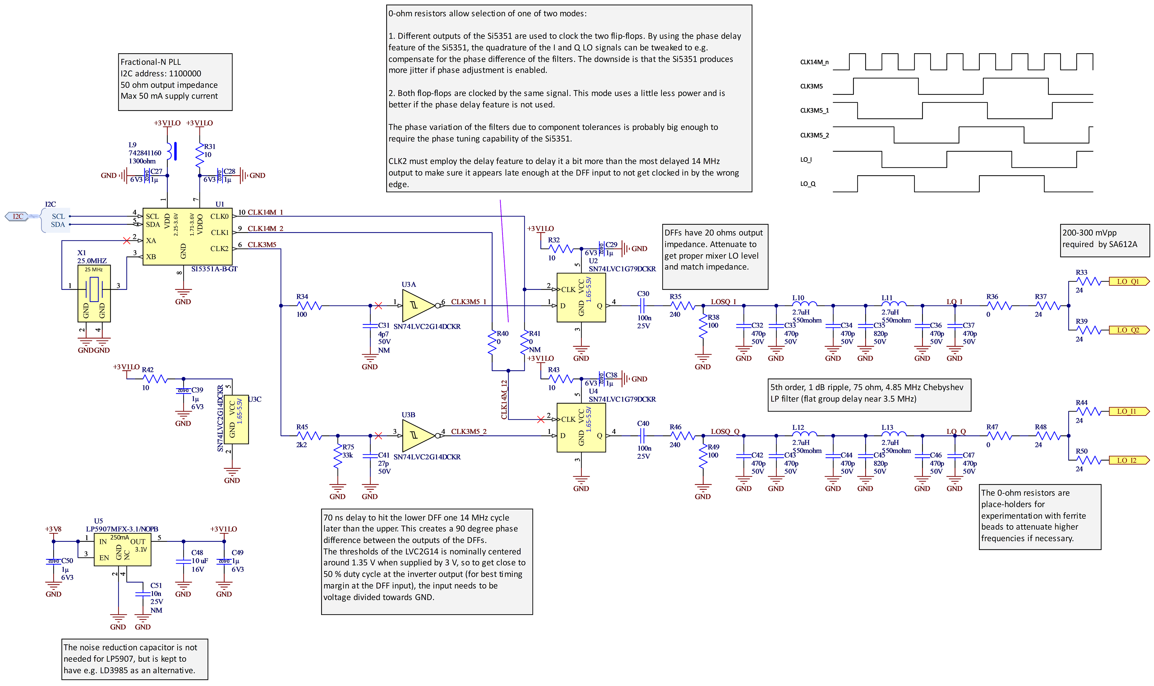
Lokaloscillatorn baseras på den populära Si5351 som kan skapa tre olika fyrkantsvågor mellan några få kHz upp till 200 MHz med så gott som obegränsad frekvensupplösning. I det här fallet skulle vi vilja ha två sinusvågor på ca 3,5 MHz (sändarens frekvens plus MF-frekvensen som är 13 kHz) i kvadratur, dvs med 90 graders fasskillnad. Si5351 kan skapa signaler med inställbar fasskillnad, men vid så låg frekvens som 3,5 MHz så räcker den inställbara tidsskillnaden inte till för att uppnå 90 grader.
Lösningen jag tänkte ut framgår av figur 23. Si5351 (U1) skapar en 3,5-MHz-signal, CLK3M5, samt två signaler med fyrdubbla frekvensen, dvs ca 14-MHz. CLK3M5 går dels via en schmittrigger-inverterare (U3A) till D-ingången på en vippa (U2) och dels fördröjs den lite via RC-länken R45/C41 innan den passerar en annan schmittrigger (U3B) som snyggar till signalen innan den når D-ingången på vippan U4. Båda vipporna klockas med väsentligen samma 14-MHz-klocka, men RC-fördröjningen gör att U2 fångar en förändring av CLK3M5 en 14-MHz-cykel tidigare än U4. En 14-MHz-cykel är 90 grader av en 3,5-MHz-cykel, så på detta sätt får man en perfekt 90 graders fasvridning. I schemat finns ett tidsdiagram för de olika vågformerna.
Figur 23. Lokaloscillator med kvadraturutgångar
R75 centrerar RC-vågformen på ingången till U3B så att den hamnar ungefär mitt för omslagspunkterna för inverteraren vilket gör att fyrkantsvågen på utgången blir så gott som symmetrisk.
Man kan finjustera fasskillnaden genom att skruva på fasfördröjningen hos de två 14-MHz-klockorna, men det är inget jag skrivit mjukvara för ännu.
Fyrkantsvågorna från D-vipporna dämpas av R35/R38 och R46/R49 samt omvandlas till sinusvågor genom två lågpassfilter med 75 ohms impedans (ingen anledning att använda 50 ohm här heller). Därefter förgrenas signalerna med varsin resistiv splitter innan de skickas vidare till mixrarna.
Efter att jag konstruerat denna lösning läste jag i byggbeskrivningen till QRP Labs mottagare QDX [5] (se sida 42 i Rev 1.12 av byggbeskrivningen) att det på något sätt verkar gå att få till kvadratursignaler även vid 3,5 MHz med Si5351. Hur detta görs i QDX verkar dock inte vara publicerat, men om man lyckas med det kan man förenkla den här kretsen och bli av med vippor, RC-länk och schmittriggrar.
Eftersom upplösningen i frekvens är fenomenal så kan man ganska lätt kalibrera frekvensen hos mottagaren så att man tar hänsyn till kristallens tolerans och får bättre än 1 ppm frekvensnoggrannhet vid rumstemperatur. I en eventuell framtida version av mottagaren kommer jag nog att förbättra detta ytterligare genom att ersätta kristallen med en TCXO (temperaturkompenserad kristalloscillator) så att inte heller temperaturvariationer ger något nämnvärt bidrag till frekvensfelet.
Så långt den analoga signalkedjan från antenn till AD-omvandling.
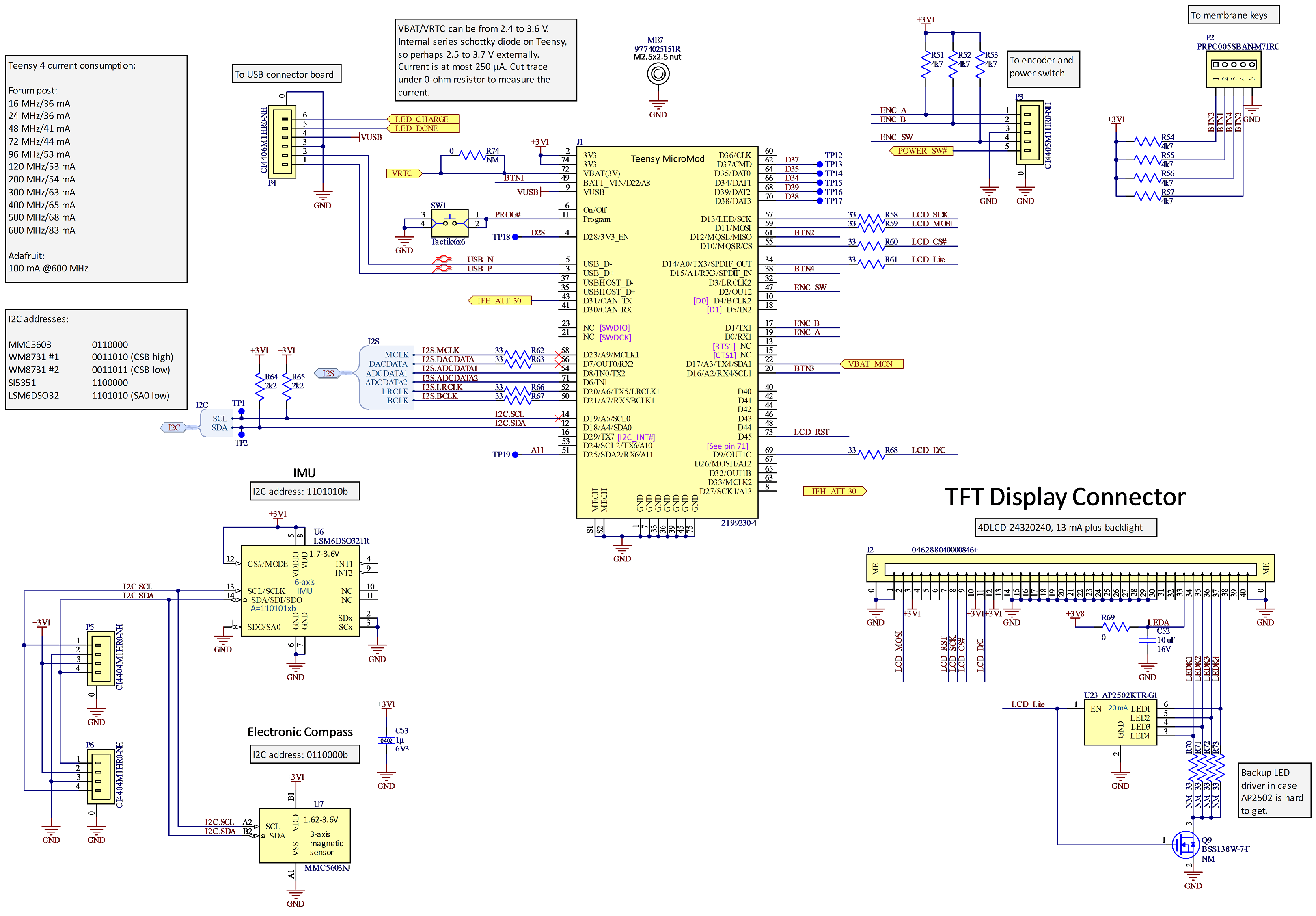
Figur 24 visar schemat med processormodulen, displayen, USB-porten, knapparna och kompasskretsarna.
Figur 24. Processor, IMU samt anslutningar till display, knappar och USB-port.
Här följer en beskrivning av signalerna motsols runt symbolen för processormodulen.
Liksom en del andra kretsar matas processorn med 3,1 V istället för 3,3 V för minskad strömförbrukning och bättre tillgänglighet på lämpliga regulatorer. Man får också fördelen att batterispänningen kan sjunka lägre innan kretsens matningsspänning påverkas. Detta är dock inte så viktigt i praktiken eftersom batterispänningen knappt sjunkit under 3,9 V även efter en och en halv timmes användning.
En standby-spänning, VRTC, som inte styrs av huvudströmbrytaren, förser realtidsklockan med matning så att tiden hålls även när resten av mottagaren är avstängd.
Fyra membrantangenter är inkopplade på signalerna BTN1-4 och avstudsas i mjukvara. Tangenterna är köpta på Electrokit (artikelnummer 41012140) och ansluts via en stiftlist med 2,54 mm delning.
Teensy-korten har en liten extraprocessor för att hantera programmering av den stora processorn och i vissa fall måste man innan programmering skicka en puls på pinnen Program till den. Därför finns en tryckknapp, SW1, kopplad till Program. I de allra flesta fall går det dock bra att programmera om även utan tryck på denna knapp, varför den sitter direkt på kortet och inte är åtkomlig med mindre än att man skruvar isär lådan.
USB-anslutningen sker via en intern kabel till ett separat litet kort med USB-kontakt och lysdioder för att indikera laddning/fullt batteri.
En signal för vardera mottagarkedjan (IFE_ATT_30 och IFH_ATT_30) avgör vilket av de två förstärkningarna med 30 dB skillnad som MF-förstärkarna ska bidra med.
Signalerna från AD-omvandlarna kommer in på I2S-bussen via I2S_ADCDATA1 och I2S_ADCDATA2. Denna buss kräver för övrigt tre klocksignaler (MCLK, BCLK och LRCLK) som skapas av processorn. Ytterligare en datasignal, I2S_DACDATA, går till DA-omvandlarna. I2S-utgångarna från processorn är försedda med serietermineringsmotstånd för bästa signalintegritet.
I2C-bussen används för att prata med Si5351, IMU-kretsarna och för att konfigurera audio-codecarna.
TFT-färgskärmen ansluts via en 40-polig FPC-kontakt och för att spara pinnar så används SPI-interfacet istället för det alternativa parallella interfacet. Bakgrundsbelysningen kontrolleras via pulsbreddsmodulering från processorn av U23, en AP2502. Jag lyckades få tag på den, men om den är otillgänglig så kan man även driva bakgrunds-LED:arna via några motstånd och Q9. Detta har dock nackdelen att ljusstyrkan blir beroende av batterispänningen som sjunker under användning. Det är viktigt att man väljer pulsbreddsmoduleringsfrekvensen så att inga övertoner hamnar i 80-m-bandet. Annars lär man höra det om man skulle tuna in övertonens frekvens.
En nerskalad version av batterispänningen är kopplad till en pinne med ADC-funktion så attman kan hålla koll på batteristatus.
En viktig del i användargränssnittet är en ratt kopplad till en ”encoder”. Ratten styr menysystemet, inställning av dämpning/förstärkning, frekvens mm. Ratten har även en tryckfunktion. Signalerna heter ENC_A, ENC_B och ENC_SW och de avstudsas i mjukvara.
U6 är en kombinerad 3-axlig accelerometer och 3-axligt gyro och den används av mjukvaran tillsammans med den treaxliga magnetometern U7 för att räkna ut en gyrostabiliserad kompassriktning hos antennen. De här två kretsarna var de komponenter jag var mest rädd för att de skulle orsaka lödproblem. U7 har en galet liten kapsel, bara 0,8 x 0,8 mm med fyra BGA-bollar på 0,4 mm centrumavstånd från varandra medan U6 är en 3 x 3 mm liten LGA med 16 anslutningar på ett avstånd av 0,5 mm. Som tur var gick lödningen bra (mer om det nedan) och jag slapp försöka rätta till besvärliga lödproblem. Ett tag övervägde jag att såga bort delen av kortet med dessa kretsar och placera på en bättre plats i lådan för att undvika störande magnetiska material, men det visade sig inte behövas och kontaktdonen P5 och P6 som var tänkta för detta fall är alltså onödiga.
Kontaktdonen som ansluter USB och knappar till huvudkortet valdes baserat på tillgänglighet (många av de populära JST-kontakterna är t.ex. svåra att få tag på för tillfället) och liten storlek. De tillverkas av Cvilux och har 1,25 mm delning. För att göra passande kablage var jag tvungen att investera i en lämplig crimptång. Efter lite googlande föll valet på en PAD-11 från Engineer. Att crimpa så här små hylsor kräver lite övning, men efter några mindre lyckade försök så gick det ganska bra att göra under mikroskop.
Det enda som återstår av schemat är spänningsmatningsdelen som visas i figur 25.
Figur 25. Strömförsörjning och laddning
LiPo-batteriet med en kapacitet på 1500 mAh och en nominell spänning på 3,7 V ansluts till P7. Batteriet är köpt på Electrokit, artikelnummer 41016064. U15 hanterar laddningen av batteriet när USB-kabeln är inkopplad. Laddströmmen är satt till ca 300 mA via R104. Två lysdioder (monterade på det separata kortet med USB-kontakt) indikerar om laddning pågår eller är klar.
Regulatorn U16 har ganska låg egenförbrukning och matas alltid av batteriet. Den skapar stand-by-spänningen till realtidsklockan i processorn. I en tidigare version av mottagaren hade jag en regulator med ännu lägre egenförbrukning, men den gick inte att få tag på när jag konstruerade denna version.
För att inte behöva dra all ström från batteriet via kontaktdon, kablar och potentiellt korroderande strömbrytare så används PMOS-transistorn Q16 för att slå av eller på strömmen till resten av mottagaren. Den styrs i sin tur av en vippströmbrytare via signalen POWER_SW#.
Linjärregulatorn U13 skapar 3,1-V-matningen till bland annat processorn. Avkopplingskondensatorerna är mestadels på 100 nF eftersom regulatorn vill se max 10 µF på utgången. Utan denna begränsning hade jag använt 1-µF-kondensatorer.
U14 är en boost-omvandlare som skapar den högre råspänning på 6 V som behövs för att driva analoga kretsar i radiodelarna. Nominell switchfrekvens är 1,6 MHz, så om det stämmer så hamnar inga övertoner i 80-m-bandet. Tyvärr är undre toleransen för switchfrekvensen 1,15 MHz, vilket gör att tredje övertonen skulle kunna komma inom bandet. Övre toleransen är 1,85 MHz, vilket gör att andra övertonen också skulle kunna göra det. I den mottagare jag byggt så var kretsen väluppfostrad och höll sig närmare nominell frekvens, men om man skulle bygga fler så är detta något att hålla ögonen på. Helst skulle man vilja ha en krets som går att synka till en väl vald extern, exakt, frekvens (kanske skapad av processorn), men jag har inte hittat någon lämplig krets för detta. Komponentbristen gör det inte lättare att hitta något passande.
SDR-mjukvara
Även om elektronikkonstruktionen, antennen och mekaniken tog en hel del tid att utveckla så är det mjukvaran jag lagt klart mest tid på.
Teensy-familjen har ett väletablerat system (audio-paketet) för att smidigt koppla ihop olika mjukvarublock som behandlar audiosignaler och i princip är detta väldigt lämpligt för att sätta ihop en signalkedja för låg mellanfrekvens och basband i en SDR-mottagare som denna där digitaliseringen sköts av audio codecs. En svaghet som jag ville undvika var dock att audio-paketet jobbar med 16-bitars fixtal, vilket kanske inte räcker för att få ut mesta möjliga signaldynamik i ett SDR-system som detta. Som tur är finns även en användarutvecklad variant som jobbar med 32-bitars flyttal [6] och som jag nyttjade. En hel del anpassningar behövde också göras i exempelvis kod för att prata med WM8731 och I2S-mottagarblocken så att 24-bitarsformat används och konverteras till flyttal.
För vanliga audiotillämpningar är det kanske inte så noga om olika audioströmmar hamnar någon millisekund fel relativt varandra, men här måste vi ha perfekt repeterbarhet på fasen mellan de två audioströmmarna. Det visade sig att audiopaketet inte var så noga med denna detalj när C++-objekten i signalkedjan skapas vid uppstart, så kod fick läggas till för att få en välkontrollerad och synkron initialisering av objekten. Tur att källkoden är öppen så att sådana ändringar är möjliga.
Själva SDR-funktionerna görs i huvudsak av ett annat färdigt mjukvarupaket, AudioSDR [7]. Detta behövde också modifieras; bland annat för att ta emot flyttal och för att lägga till några nya alternativa MF-filter. Dessa filter designas ganska smidigt med hjälp av gratismjukvara från Iowa Hills, men någon gång nyligen verkar hemsidan där alla filterdesignprogrammen fanns att ladda ned ha försvunnit. Det finns dock ett GitHub-repo där man kan ladda ned källkoden [8]. Många av finesserna i AudioSDR är inte nödvändiga i denna pejlmottagare. T.ex. är AGC och AM-mottagning inte av intresse, men MF-filtreringen, den komplexa nedblandningen till basband och Hilbertfiltreringen som gör att man kan undertrycka det oönskade sidbandet passar perfekt för applikationen. Hur undertryckning av sidband går till med denna metod (”phasing”) går jag inte närmare in på, utan hänvisar till avsnitt 9.2 i [4] som ger en gedigen genomgång av inte bara matematiken bakom, utan även av analyserar olika felkällors inverkan på resultatet. En framtida förbättring av mottagaren vore att införa rutiner som möjliggör finjustering av signalnivå och fas före Hilbertfiltreringen för optimal sidbandsundertryckning.
Efter att basbandssignalerna för de två mottagarkedjorna vaskats fram är det dags för lite mer specialiserad och hemsnickrad signalbehandling för att analysera framförallt fasskillnaden mellan signalerna från de två antennerna. Denna signalbehandling går till som följer:
Först kastas vartannat sampel bort för att minska beräkningsbördan något. Detta kan göras eftersom signalen redan är bandbegränsad av MF-filtret till långt under en fjärdedel av samplingstakten (44,1 kHz), så en halvering av samplingstakten till 22,05 kHz orsakar ingen nämnvärd vikningsdistorsion.
Nästa steg är att göra överlappande ”FFT:er” (Fast Fourier Transform, samma matematiska beräkning som används vid vattenfallsdisplayer och alltså delar upp signalen i olika frekvenskomponenter) av längd 1024 på signalen från E-fältsantennen (eftersom den alltid finns tillgänglig, medan H-fältsignalen är väldigt svag vid sitt minimum). Det ger en frekvensupplösning på 22,05 kHz/1024 = 21,53 Hz. Före FFT:n läggs ett Gauss-fönster på signalen för att inte få ”kjolar” och för att den följande frekvensuträkningen ska bli mer exakt.
FFT:n söks igenom för att se om det någonstans finns en topp som sticker ut och om det gör det så behöver frekvensen för den tonen beräknas. Det görs genom att väga samman styrkan hos det starkaste facket i FFT:n och de omedelbart närliggande facken enligt metoden i [8], vilket ger ett mycket noggrannare estimat av frekvensen än att rakt av välja mittfrekvensen för det fack som hade starkast signal.
Nu vet vi vilken frekvens som vi har tagit emot och som fasjämförelsen ska göras vid. Fasjämförelsen görs i tidsdomänen på följande vis: Först skapas syntetiska sinus- och cosinussignaler av längden 1024 med den uppmätta frekvensen. Därefter multipliceras 1024 sampel av vardera signalen från E-mottagaren och H-mottagaren, sampel för sampel, med dessa syntetiska signaler och resultaten ackumuleras. Det handlar alltså om att räkna ut korrelationen mellan respektive signal och sinus- samt cosinus-signalerna. Dessa två korrelationer, låt oss kalla dem sincorr_E, coscorr_E samt sincorr_H och coscorr_H, visar vilken fas som signalen har relativt den påhittade sinussignalen. Nu är det bara att räkna ut arctan(sincorr_E/coscorr_E) och arctan(sincorr_H/coscorr_H) för att få fram respektive fasvinkel. Dessa vinklar i sig säger inte något intressant, men skillnaden mellan dem är precis vad vi är ute efter. Så en enkel subtraktion mellan dem visar nu den önskade fasskillnaden mellan E-fält och H-fält!
Om antenn och mottagare fungerar som de ska så är det nu bara att svepa med mottagaren i ungefärlig riktning mot sändaren och se i vilken riktning denna fasskillnad gör ett hopp på 180 grader, samtidigt som H-signalen har ett minimum. Beroende på fasvinklarna till vänster och till höger om hoppet kan man avgöra om man har sändaren framför eller bakom sig, så separat sidbestämning blir överflödig.
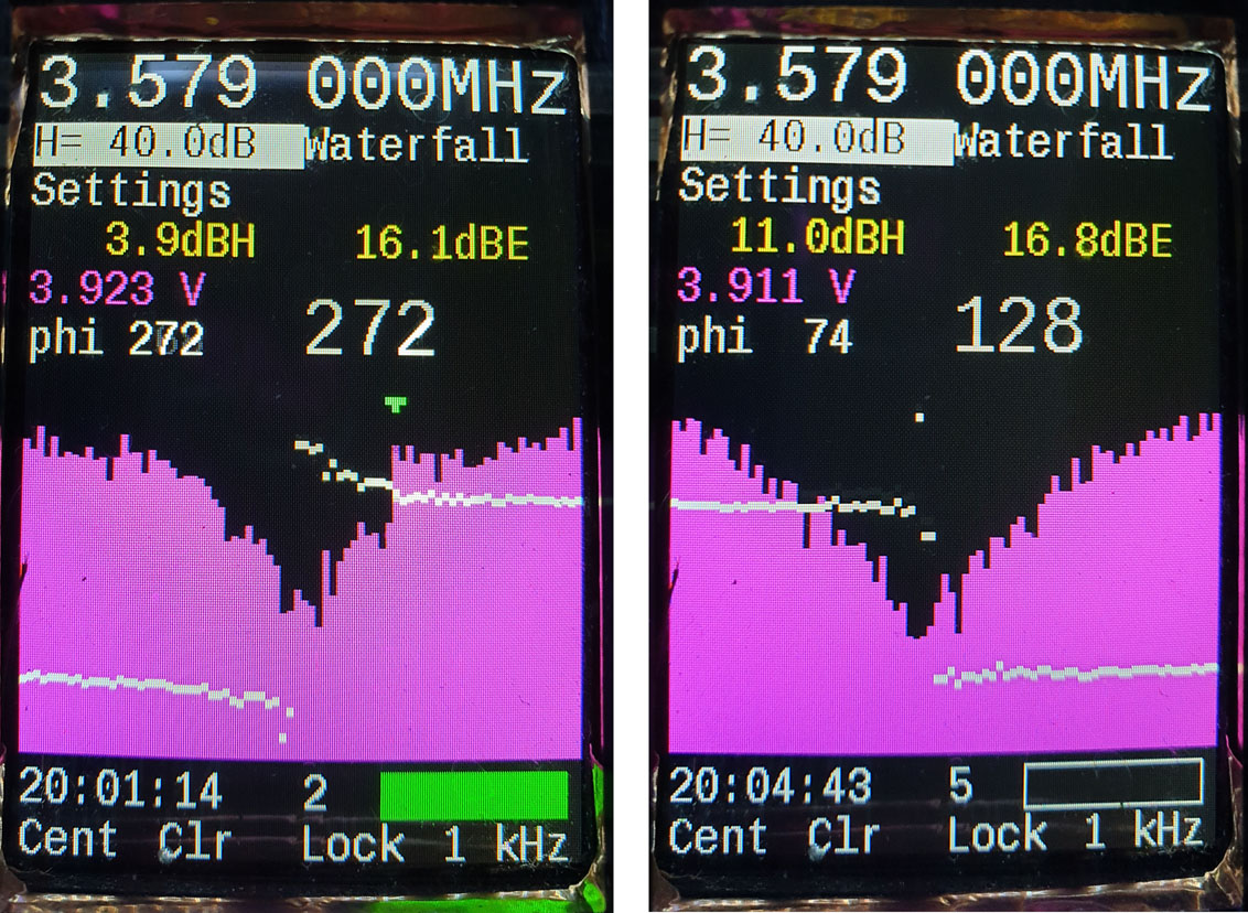
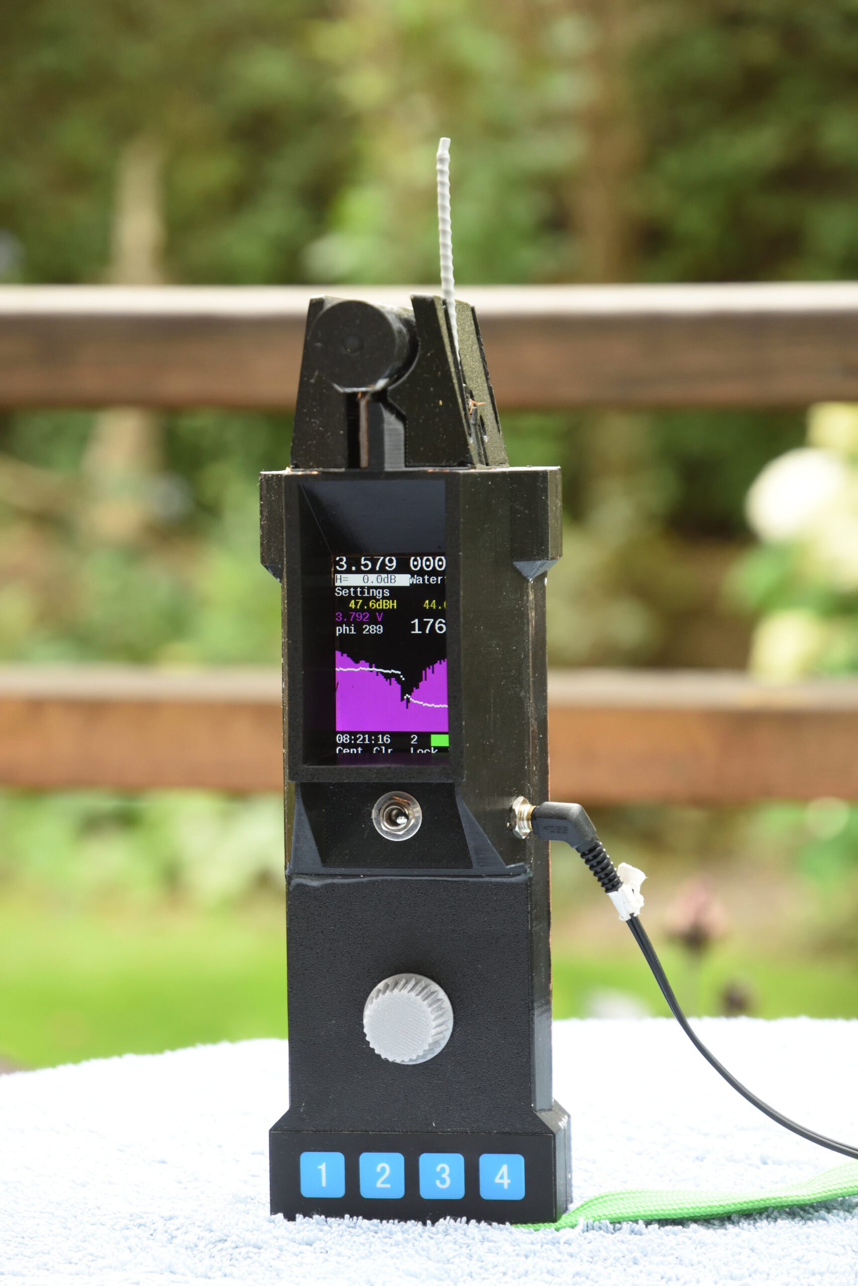
Figur 26 visar hur displayen kan se ut när man pejlar först bort från sändaren och sedan mot den. De violetta staplarna visar signalstyrkan från H-antennen i olika kompassriktningar man svept över, medan de vita markeringarna visar fasskillnaden mellan E och H. Bredden på displayen täcker i detta fall 80 grader av kompassvarvet. Som synes finns ett minimum i mitten av bilden i båda fallen, men i vänstra fallet är fasskillnaden låg till vänster om mitten och hög till höger om mitten, medan förhållandet är det omvända i högra bilden. Om man vet att mottagaren mäter upp en hög fas när man pekar till vänster om sändaren och en låg när man pekar till höger så kan man genast avgöra om minimat/fashoppet man hittat är det önskade, eller om man måste rotera ett halvt varv för att vara vänd mot sändaren.
Figur 26. Skärmbilder efter pejling bort från sändaren respektive mot den.
Övrig mjukvara
Det går att få in mycket mer än de rena SDR-funktionerna i mjukvaran och en del av finesserna som lagts till kan anas i skärmbilderna i figur 26. Under en tävling tittar man normalt inte på någon annan vy än den i figuren, men före en tävling kan man göra ett antal inställningar, kalibreringar och även titta på olika typer av debuginformation som kan vara intressant under utvecklingen.
En av de mer komplexa funktionerna är hanteringen av IMU:n, dvs kompassen. Ett s.k. Kalmanfilter väger samman informationen från accelerometer, gyro och magnetometer för att estimera hur mottagaren är orienterad relativt jordytan och magnetiska norr. Som tur är finns det färdiga bibliotek som utför denna komplexa matematiska algoritm och jag valde att använda Kalmanfilterkod utvecklad av NXP, men ompaketerad av Adafruit, se [10]. I princip ser man bara till att förse Kalmanfiltret med periodiska uppdateringar (ca 100 gånger i sekunden i detta fall) av mätvärden från sensorerna och kan sedan när som helst fråga det i vilken riktning som antennen pekar.
Själva användargränssnittet kräver lite omtanke för att fungera bra i en tävlingssituation. Som nämnts tidigare så består det förutom av skärm och hörlurar av fyra knappar plus en encoder med knappfunktion. När man slår på strömmen startar den upp på en förprogrammerad frekvens och ratten styr förstärkningen. Vad de fyra membranknapparna gör framgår av text i nederkanten av skärmen. I figur 26 är funktionerna i tur och ordning: centrera plotten i nuvarande pejlriktning, rensa innehållet i plotten, lås till sändarens frekvens, respektive växla mellan olika filterbandbredder från 100 Hz till 3 kHz.
På skärmen visas förutom pejlingsplotten, även lite annan information som nuvarande frekvens, förstärkning, signalstyrkor, batterispänning, aktuell fasskillnad mellan E och H (phi), kompassbäring, aktuell tid, vilken räv som sänder och ett färgat fält som anger vilken färg på penna jag valt att använda för aktuell räv. Jag brukar springa omkring med fem olika pennor runt halsen och i hastigheten kan man lätt ta fel när man ska rita in en bäring på kartan. Speciellt på SM i 80 m när sju olika rävar är igång och det bara finns fem färger att välja på kan det vara bra med detta stöd.
Vid sprinttävlingar programmerar jag in de fyra aktuella frekvenserna i förväg och Lock-funktionen ersätts då av en funktion för att växla mellan de fyra frekvenserna.
Kretskort
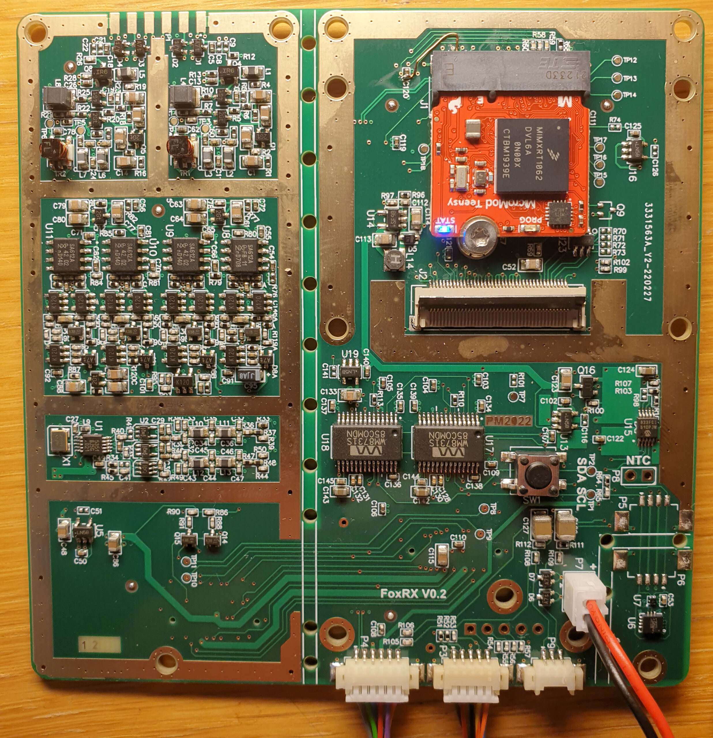
Mönsterkortet har fyra lager för att inte behöva kompromissa med jordplan och signalintegritet. Det är tillverkat hos JLC PCB till en rimlig kostnad tillsammans med en pastastencil som möjliggör att man applicerar lodpasta på alla lödytor. Alla ytmonterade komponenter förutom två kontaktdon sitter på en och samma sida av kortet. Figur 27 visar det bestyckade kortet.
Figur 27. Ovansidan av kretskortet innan det sågades isär.
Antennsignalerna kommer in uppe till vänster, förstärks och skickas vidare nedåt där de mixas i de fyra SO8-kretsarna. Under rutan med mixrar och MF-förstärkare finns en ruta med lokaloscillatorn. På högra delen av kortet finns längst ned kontaktdon för USB, encoder, hörlurar och batteri. Nere i högra hörnet sitter IMU-komponenterna. Högre upp finns Program-knapp, de två audio-codecarna, laddkrets, displaykontakt och den röda modulen med processorn.
Montering och lödning av kortet gick till som så att jag först tryckte på lodpasta med hjälp av stencilen, sedan tillbringade runt fyra timmar med att med pincett under mikroskop plocka på de över 300 komponenterna och sedan värma upp kortet underifrån via en tjock stålplåt ovanpå induktionshällen i köket. I förväg hade jag testat fram ett recept med tider och effektinställningar som gav en vettig temperaturprofil. Lödningen gick riktigt bra och det enda jag behövde åtgärda var ett par lodbryggor vid display- och processorkontakterna.
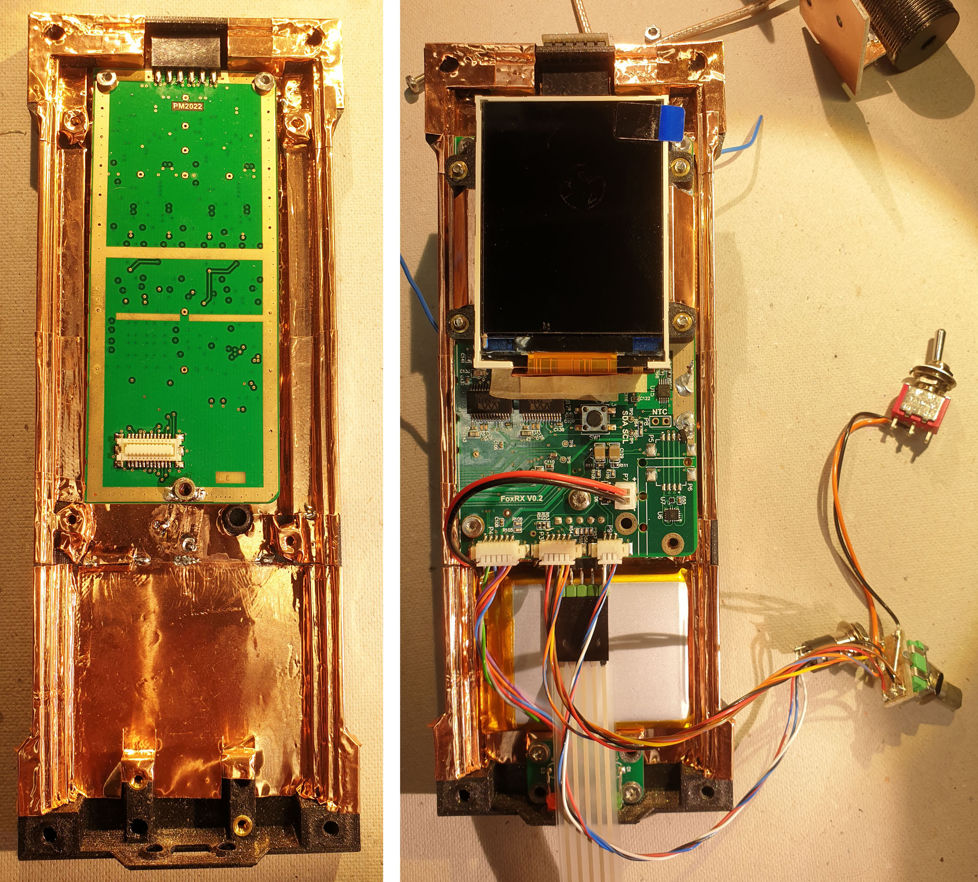
När en hel del av funktionerna var provkörda var det dags att såga isär kortet mellan de vertikala linjerna och montera ihop det som en dubbelmacka via ytmonterade kontaktdon på undersidan av kortet. Se figur 28.
Figur 28. Korten efter isärsågning och hopkoppling.
Mekanik
Jag valde att tillverka lådan för mottagaren genom att rita ihop 3D-modeller och skriva ut på 3D-skrivare. Det har blivit några iterationer och nuvarande utseende är kanske inte det slutgiltiga. För att skärma av elektroniken i mottagaren så att störningar från elektroniken inte kopplas in i antennen så är lådan skärmad invändigt med hjälp av koppartejp. Skarven mellan lådhalvorna överbryggas av en ledande packning. Kretskorten är jordade till koppartejpen på många punkter via små fjäderbelastade pogo-pinnar. Se figur 29.
Figur 29. Jordande pogo-pinnar har lötts på RF-kortet.
Rent allmänt är en slutsats från experiment med en tidigare prototyp att det lönar sig mycket mer att försöka skärma in störande kretsar än att skärma känsliga kretsar.
Antennerna är ju avsiktligt gjorda för att plocka upp svaga signaler och de är kopplade till de känsligaste punkterna i signalkedjan, så att inte skicka ut störningar som når antennerna är högsta prioritet. Processorkort och display är två av de värsta störgeneratorerna och av den anledningen får plattformen som displayen är monterad på göra dubbel nytta genom att även vara bas för koppartejp som omsluter processormodulen och utgör ett jordplan nära displayen.
Med korten färdigbestyckade kan det hela monteras i lådan, se figur 30.
Figur 30. Stegvis montering av mekanik och elektronik.
En liten utmaning var genomföringen av antennsignalerna genom lådväggen. Valet föll till slut på en 12-polig hylslist på RF-kortet med de flesta benen jordade för skärmning och använda en lång stiftlist uppe vid antennerna som fick sticka in via utskrivna hål i lådan. Detta gör monteringen av olika delar enkel och oberoende. Specialkonstruerade lådor utskrivna på 3D-skrivare ger sådana trevliga möjligheter. Att ha kontaktdon mellan antennen och RF-kortet har den extra fördelen att det blir lätt att direkt koppla in en signalgenerator eller nätverksanalysator för att göra mätningar på kortet.
För att få bra läsbarhet på displayen även i solljus valde jag att bygga upp skuggande väggar runt den. Det möjliggör också att man sätter koppartejp runt dessa väggar och förhoppningsvis får lite mindre läckage av störningar via detta nödvändiga hål i skärmningen.
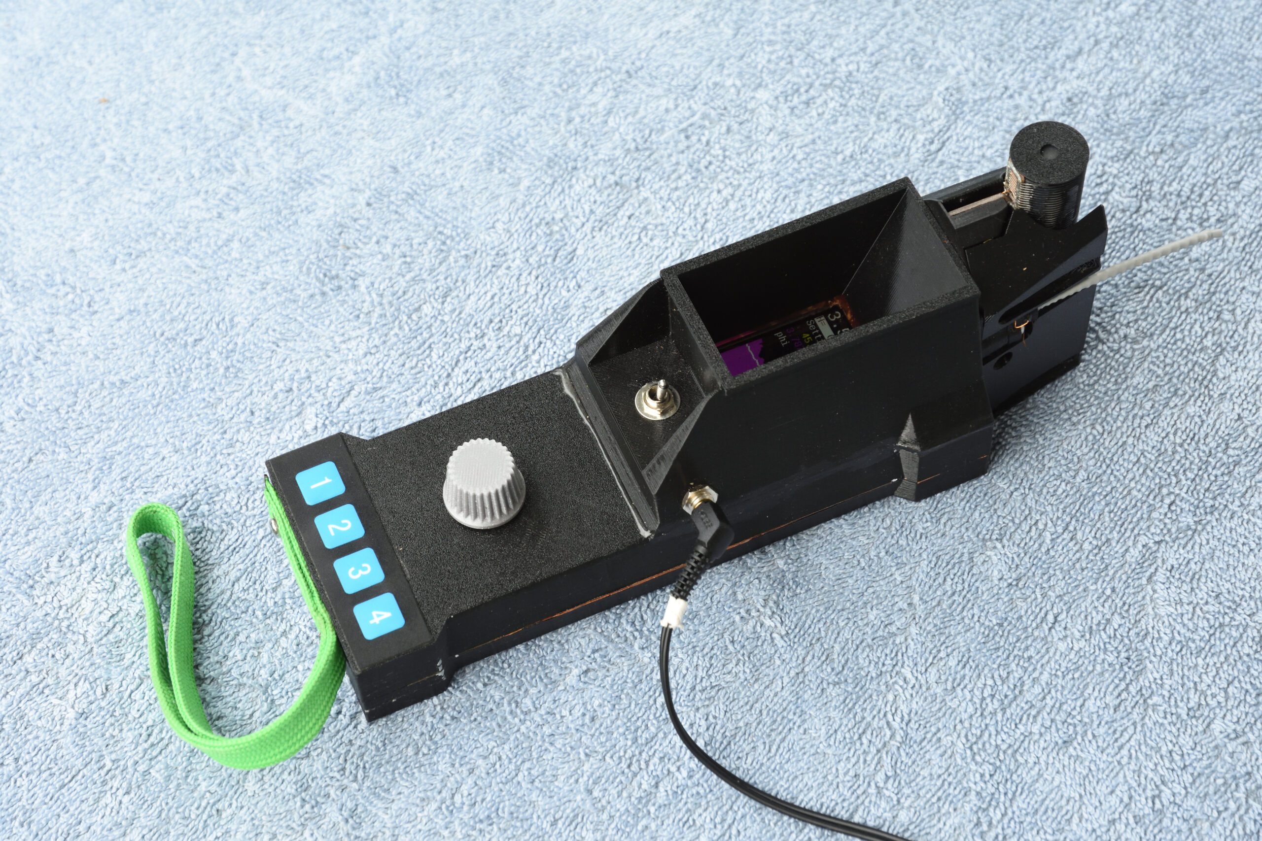
Ratten som styr menysystemet sitter mitt på nederdelen av lådan och under den sitter de fyra membranknapparna. Se figur 31.
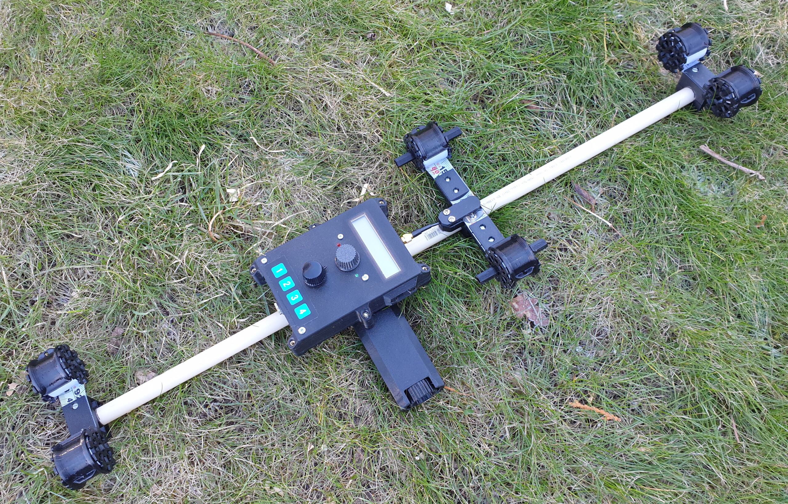
Figur 31. Färdigbyggd mottagare
Ytterligare en idé jag lånat från 80m12 är att ha ett handledsband fäst i mottagaren så att man kan släppa den och låta den dingla t.ex. när man vrider in en kompassriktning och ritar bäringar på kartan.
För att få skruvarna att fästa i plasten användes gängade insatser av mässing som värmdes ned i lämpliga hål med hjälp av en lödpenna inställd på knappt 300 grader. Enbart rostfria skruvar användes för att störa magnetometern så lite som möjligt. Även muttrarna till strömbrytare och hörlursuttag valdes för att vara omagnetiska.
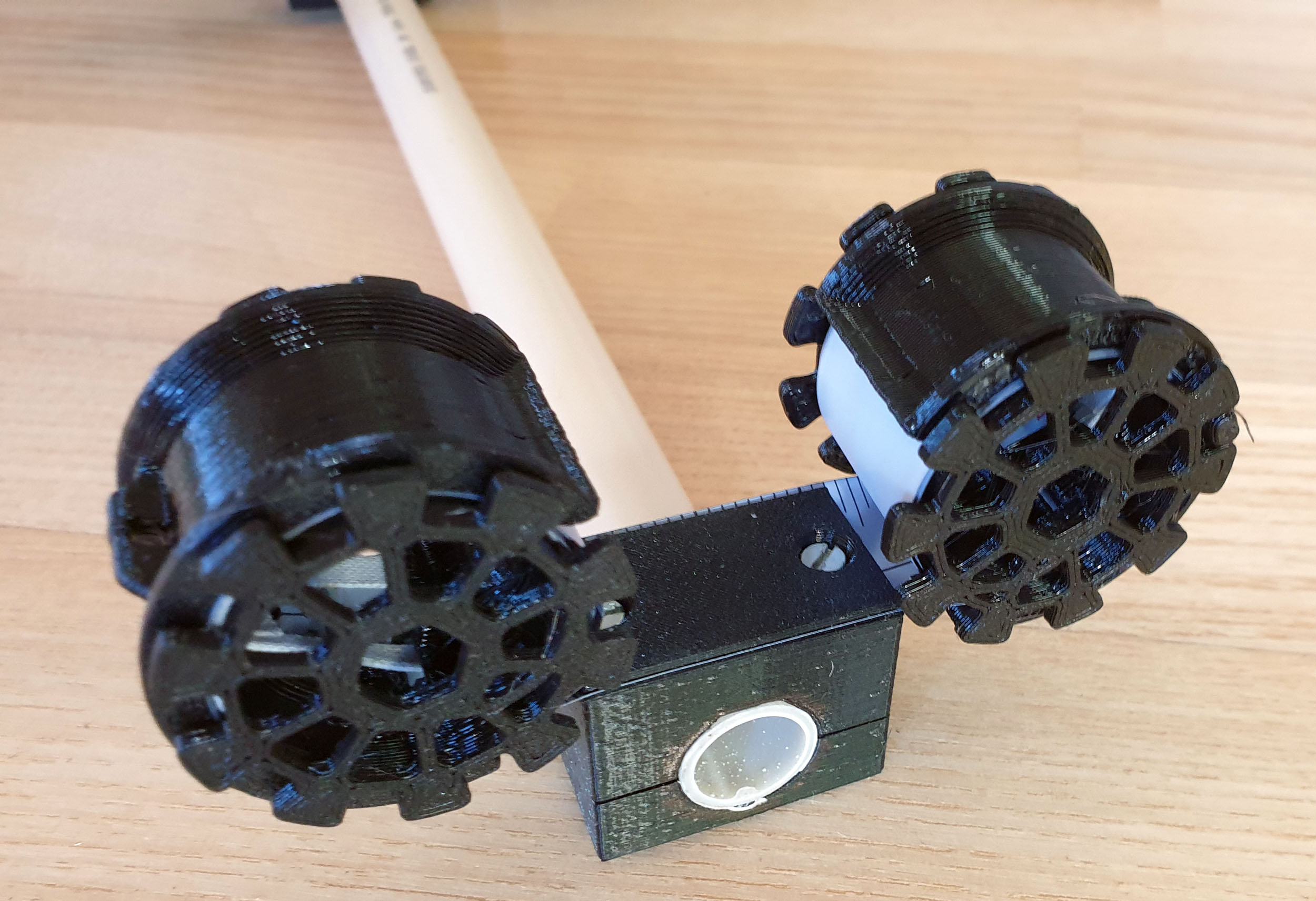
Antennerna sitter ihop i en ganska komplex 3D-utskriven modul som håller dem på bra positioner och skyddar mot stötar.
Det hela är såklart inte perfekt vattentätt, men om det väntas regn kan man förbättra situationen något genom att tejpa skarven mellan lådhalvorna.
Nuvarande hölje är utskrivet i materialet PETG, vilket är ganska segt och tåligt. En tidigare version var utskriven i PLA, men den plasten är ganska skör och gick delvis sönder när jag snubblade på en tävling.
Slutord
Med en till stora delar mjukvarubaserad mottagare så går det att införa nya finesser och förbättringar utan omfattande omkonstruktion. Även på hårdvarusidan finns det såklart förbättringar att göra och nuvarande version måste nog ses som en prototyp med förbättringspotential, även om jag i princip uppnått i stort sett allt jag tänkte mig när jag drog igång det här projektet och har tävlat med den med viss framgång.
Att utveckla den här mottagaren har varit lärorikt och kul (och tämligen tidskrävande) och jag hoppas att redogörelsen kan inspirera andra att ta fram nya innovativa pejlmottagare eller låna idéer och lösningar till mer traditionella mottagare.
Det här blogginlägget är första delen i en artikelserie där jag beskriver en mottagare (“rävsax”) för radiopejlorientering på 80m-bandet. En snarlik variant av artikeln publicerades i Sveriges Sändaramatörers, SSA:s, tidskrift QTC med början i nummer 10, 2022.
Denna första del beskriver bakgrunden till projektet, hur radiovågor, antenner och pejling fungerar på 80m-bandet samt hur jag valde att tillverka antennerna.
FoxScope
Såvitt jag kan komma ihåg så har det inte publicerats någon artikel om radiopejlmottagare (rävsaxar) i QTC på över 10 år. I nummer 2, 2012 beskrev Bo Lenander sin eleganta 80m12-konstruktion; en artikel som jag läste med stort intresse [1]. Jag var redan då sedan flera år nyfiken på radiopejlorientering/rävjakt, men hade aldrig testat sporten och hade ingen koll på hur sådana mottagare brukar vara uppbyggda. Vad ”sidbestämning” är och hur den finessen fungerar förstod jag inte heller.
Sedan dess har jag fått chansen att prova på sporten ett antal gånger, med första tillfället i maj 2019 då tävlingar arrangerades i Linköping där jag bor. Mottagaren jag lånade för 80-m-tävlingen visade sig vara en nyare variant av just 80m12-konstruktionen och poängen med sidbestämning blev genast uppenbar. Som orienterare och elektronikkonstruktör med radiointresse var radiopejlorientering en mycket positiv upplevelse och förutom att börja åka på tävlingar så kom även funderingarna på hur jag skulle kunna bygga en egen mottagare med ännu bättre egenskaper. Jag lekte med tankar på en direktsamplande arkitektur med en FPGA för signalbehandlingen (vilket påminner om system jag konstruerar på arbetstid) och en uppblandande superheterodyn med kristallfilter, men jag fastnade till slut för en (nästan) direktkonverterande mottagare (låg-MF) med spegelfrekvensundertryckning där den låga mellanfrekvensen (13 kHz) samplas av 24-bitars audio-codecar och resten av signalbehandlingen görs i en mikroprocessor.
Genom att kosta på mig en konstruktion med högre komplexitet än andra radiopejlmottagare jag stött på hoppades jag kunna åstadkomma en mottagare som gör det möjligt att snabbare och mer noggrant pejla riktningen till sändarna (rävarna). Den bärande – och möjligen nya – idén var att ha två parallella mottagarkedjor så att man samtidigt kan ta emot signalerna från både H-fältsantennen och E-fältsantennen och jämföra deras fas för att noggrant kunna avgöra precis när H-fältsantennen sveper förbi riktningen mot sändaren. När det inträffar får man (som bekant?) både ett minimum i signalen från H-fältsantennen (vilket utnyttjas av alla kända pejlmottagare) och dels ett fashopp på 180 grader i samma signal. Signalen från E-fältsantennen däremot har samma fas hela tiden och kan således utgöra referens vid fasjämförelsen. En del ferritantenner ger ett lite diffust minimum, men om antennen är väl skärmad från E-fältet bör fashoppet ske i en väldigt distinkt riktning. Åtminstone i fjärrfältet. På köpet kan man skilja på om antennen pekar mot sändaren eller bort från den, vilket eliminerar det extra momentet med sidbestämning som krävs i traditionella mottagare.
Sammantaget hoppades jag kunna uppnå bland annat följande egenskaper och finesser i min konstruktion:
Eliminering av det separata sidbestämningsmomentet.
Snabbt få fram en distinkt pejlriktning.
Mottagning av endast enkelt sidband för att slippa störningar och brus från spegelbandet. Detta kan vara speciellt viktigt på nattävlingar då allsköns avlägsna stationer kan dundra in. Eller på tävlingar som går nära bebyggelse med diverse störkällor.
Kristallstyrd och kalibrerad lokaloscillator för att slippa osäker och drivande frekvensinställning.
Ett antal olika valbara filterbandbredder för att kunna göra olika avvägningar mellan att få lågt brus och möjligheten att höra rävar som ligger lite fel i frekvens.
Så bra elektrisk skärmning av ferritantennen som möjligt.
Inbyggd elektronisk kompass.
En grafisk skärm så att mottagaren kan visa signalstyrka och fasskillnad som funktion av kompassriktning.
Realtidsklocka för att hålla reda på vilken räv som sänder.
LiPo-batteri för låg vikt och laddbarhet.
Saker jag kunde tänka mig att pruta på var att konstruktionen inte behövde vara särskilt enkel, billig eller snabbutvecklad. Men jag ville att den ändå skulle vara möjlig för mig att bygga utan att anlita en professionell elektronikmonteringsfabrik.
Antenner och vågor vid rävjakt
Innan jag beskriver hur mottagaren – som jag kallar FoxScope – fungerar tänkte jag ge lite bakgrund om hur pejling vid 80 m rävjakt går till.
I en traditionell radiopejlmottagare för 80 m så har man två antenner. Huvudantennen är antingen en enkel loop utan kärna (typiskt en eller två decimeter i diameter) eller så är det en ferritstav med spole. Denna antenn tar emot magnetfältsdelen (H-fältet) av radiovågorna. Man har även ett litet vertikalt spröt som tar emot det elektriska fältet. Av nödvändighet är antennerna väldigt mycket mindre än våglängden och därmed tämligen ineffektiva, men de är ändå tillräckligt bra för att kunna snappa upp sändningen från en typisk räv på några km avstånd.
Jag valde att använda en ferritantenn som huvudantenn och resten av beskrivningen är baserad på det.
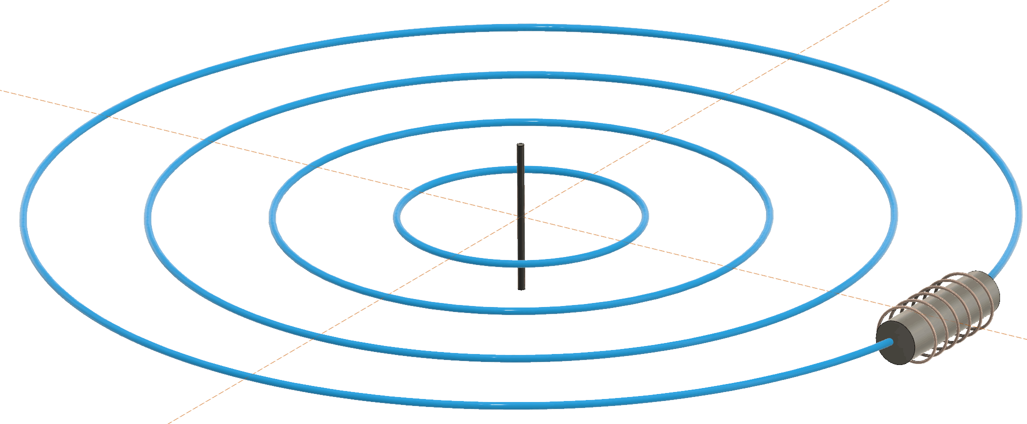
Sändarna (rävarna) skickar ut signaler i form av nycklad CW, dvs en enkel omodulerad ton som slås av och på i form av morsetecken. Sändarantennen är vertikalt polariserad, vilket innebär att det elektriska fältet i markplan är vertikalt riktat medan det magnetiska fältet är horisontellt i form av cirklar som breder ut sig från sändarantennen.
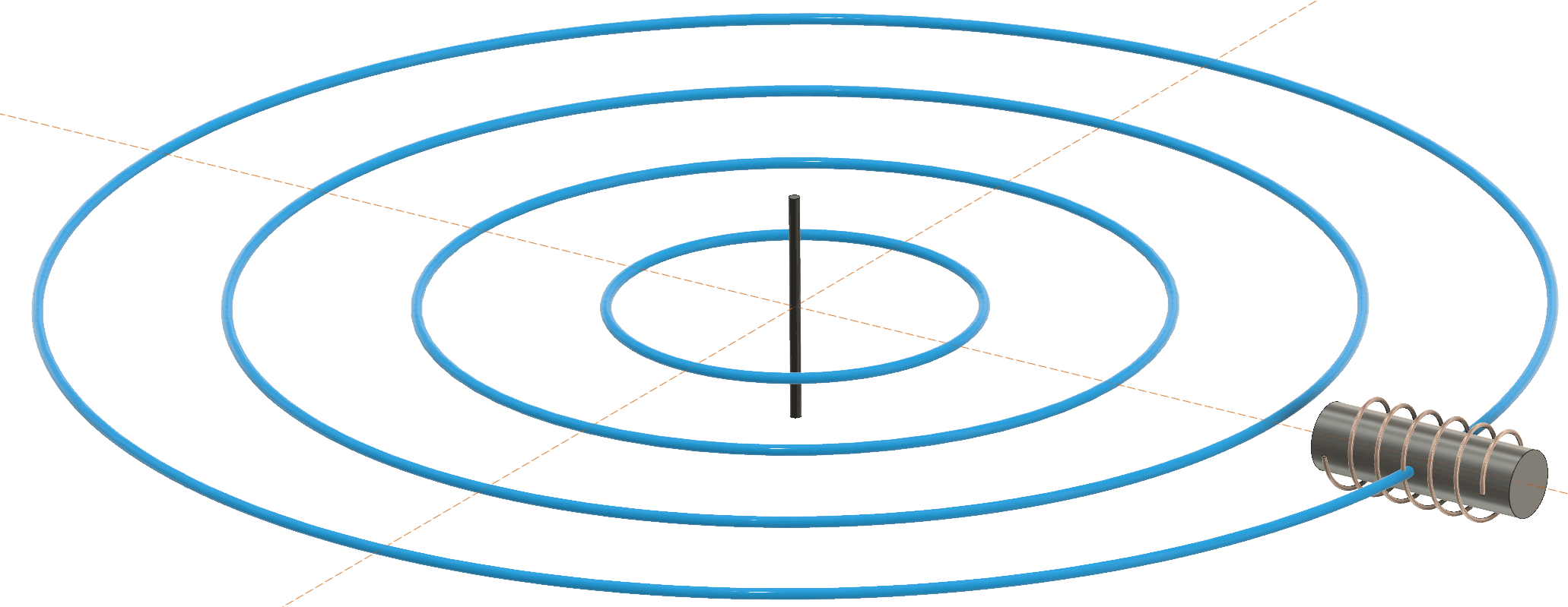
När man håller ferritstaven parallellt med magnetfältet så fångar man upp maximalt med magnetiska fältlinjer och man får maximal signal, vilket visas i figur 1. Om man vrider staven så att den pekar mot sändaren kommer inga fältlinjer att passera genom spolen och man får minimal signal enligt figur 2. Fortsätter man att vrida antennen så får man återigen en signal, men med 180 grader skillnad i fas mot tidigare.
Figur 1. Ferritantennen ger maximal signal när bredsidan är riktad mot sändaren. De blå cirklarna visar de magnetiska fältlinjerna från sändarantennen i mitten av bilden.Figur 3. När ferritantennen pekar rakt mot sändaren ger den minimal signal.
Maximat i en sådan här antenn är väldigt diffust, men minimat är i bästa fall tydligt, så det är det man traditionellt använder för att pejla sändarna. Ett ungefärligt antenndiagram visas i figur 3. På grund av symmetrin finns det ett minimum i ferritstavens båda riktningar, så om man inte på något annat sätt vet vilken av dessa två motsatta riktningar som pekar mot sändaren så behövs en metod för att ta reda på det.
Figur 3. Antenndiagram för ferritantenn.
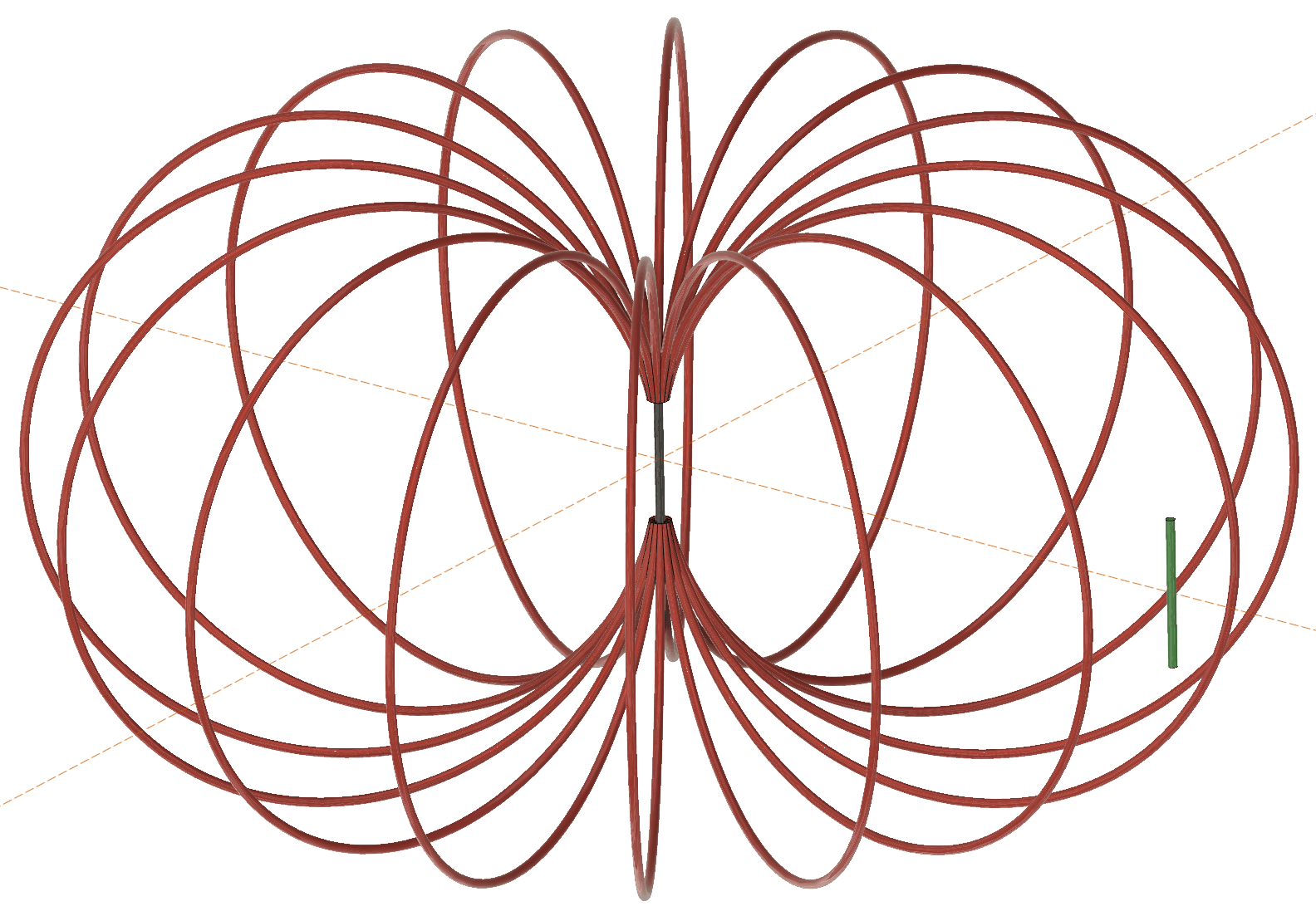
E-fältsantennen pekar alltid uppåt när man pejlar och ger därför lika stark signal med samma fas oavsett hur man roterar mottagaren runt vertikalaxeln. Se figur 4.
Figur 4. Fältlinjerna hos E-fältet (röda kurvor) går vertikalt vid den gröna E-fältsmottagarantennen och varken fas eller amplitud på signalen som antennen plockar upp påverkas av hur antennen är roterad runt vertikalaxeln. (I praktiken så gör den ledande marken att undre delen av fältet ser ut på ett annat sätt än i figuren.)
I 80m12 och många andra mottagare finns en knapp som om den hålls in aktiverar även E-fältsantennen och adderar signalen från den till signalen från ferritantennen. Om signalerna är lika starka (något man strävar efter i konstruktionen) vid summationspunkten och inte har drabbats av olika fasvridningar så är de i motfas och släcker ut varandra om man har ena bredsidan av ferritantennen mot sändaren medan signalerna är i fas och adderas om andra bredsidan vänds mot sändaren. Rävjägaren jämför vilken av bredsidorna som ger starkast signal och kan därmed avgöra vilken av de två riktningarna som är den sanna.
En pejling går alltså till som så att man först pejlar tills man hittar ett minimum. Nu vet man att sändaren ligger på linjen genom ferritstaven, men inte i vilken av de två riktningarna den finns. Sedan vrider man mottagaren 90 grader för att få ett maximum och trycker in sidbestämningsknappen. Därefter testar man om denna position av mottagaren ger starkare eller svagare signal än om man roterar mottagaren ytterligare 180 grader. Med denna information kan man avgöra om sändaren finns framför eller bakom en.
Figur 5 visar hur signalerna ser ut för fyra olika riktningar hos mottagaren relativt sändaren. Röda kurvor är signalen från E-fältsantennen, blå kurvor är från ferritantennen medan gröna visar resultatet av additionen av dessa två när man trycker in sidbestämningsknappen. De översta kurvorna visar när bredsida 1 av ferritantennen är riktat mot sändaren. Båda signalerna är starka och i fas, så när man sidbestämmer får man en stark signal.
Nästa kurvor visar vad som händer när ferritantennen har vridits så att den nästan pekar mot sändaren, men utan att dess förlängning passerat sändaren. Nu är H-fältsignalen (blå) svag, men har fortfarande samma fas.
Tredje gruppen kurvor visar fallet att ferritantennens förlängning svept aningen förbi sändaren. Signalen är även nu svag, men har fått omkastad fas.
De nedersta kurvorna visar hur det ser ut när mottagaren vridits så att andra bredsidan av ferritantennen pekar mot sändaren. Nu är H-fältsignalen återigen stark, men denna gång i motfas mot E-fältsignalen, så additionen vid sidbestämning ger en svag signal.
Figur 5. Signaler från de två olika antennerna vid fyra olika riktningar hos mottagaren. Röda kurvor är från E-fältet, blå från H-fältet (ferritantennen) och gröna är resultatet av additionen mellan signalerna när man gör sidbestämning.
I praktiken kan det vara svårt att få signalerna från de två antennerna att vara lika starka och i perfekt fas/motfas vid sidbestämning, så för att få en tydlig sidbestämning kan man behöva höja och sänka mottagaren mellan knähöjd och över huvudhöjd i förhoppningen om att på någon höjd över marken hitta en position där signalerna från antennerna är ungefär lika starka och det därför blir tydligt vilken av sidorna som ger starkast signal.
Antennskärmning
En annan svårighet som jag upplevde med den mottagare jag lånat är att minimat vid pejling ganska ofta inte är särskilt tydligt. Dock lärde jag mig att det gick att få det tydligare genom att hålla ena handen en decimeter över antennen under pejlingen. Jag tror dessa fenomen beror på att ferritantennen inte är särskilt väl skärmad från det elektriska fältet så även när den är riktad så att den inte ger någon signal från magnetfältet så plockar den upp en signal från E-fältet som suddar ut minimat. Handen över antennen skärmar i någon mån av E-fältet och gör minimat tydligare och pejlingen därmed exaktare.
I många pejlmottagare man kan köpa färdiga är ferritantennen inbyggd i en skärmad låda (ofta gjord av mönsterkortslaminat ser det ut som) med en slits i kopparfolien i samma riktning som ferritstaven. Skärmningen gör att E-fältet inte kommer åt spolen medan slitsen gör att skärmningen inte agerar som ett kortslutet lindningsvarv, vilket annars kraftigt skulle minska dess känslighet. Se figur 6.
Figur 6. Ferritantenn med E-fältsskärm med slits på ovansidan.
Att ha en – bortsett från slitsen – heltäckande folie runt ferritantennen borde ändå i någon mån dämpa magnetfältet när fältlinjerna inte är parallella med ferritstaven. Då tvingas nämligen fältlinjerna passera genom metallfolien så att virvelströmmar induceras, magnetfältet dämpas och minimat borde bli bredare. Se figur 7.
Figur 7. Om ferritantennen inte är parallell med magnetfältet passerar magnetiska fältlinjer (blå) genom sidorna på slitsskärmen som borde dämpa signalen och bredda minimat.
Så kanske vore det ännu bättre att ha en skärm med inte bara en slits längs med ferriten, utan väldigt många fler slitsar även i andra riktningen så att skärmen inte har sammanhängande metallytor som det kan induceras virvelströmmar i?
Ett sätt att uppnå det är att använda en bred flatkabel som skärm, löda ihop alla ledarna under ferritstaven och kapa flatkabeln ovanför antennen. Se figur 8.
Figur 8. Principen för en ”flatkabelskärm” (röda ledare) med slits på ovansidan och sammankopplad jordning på undersidan.
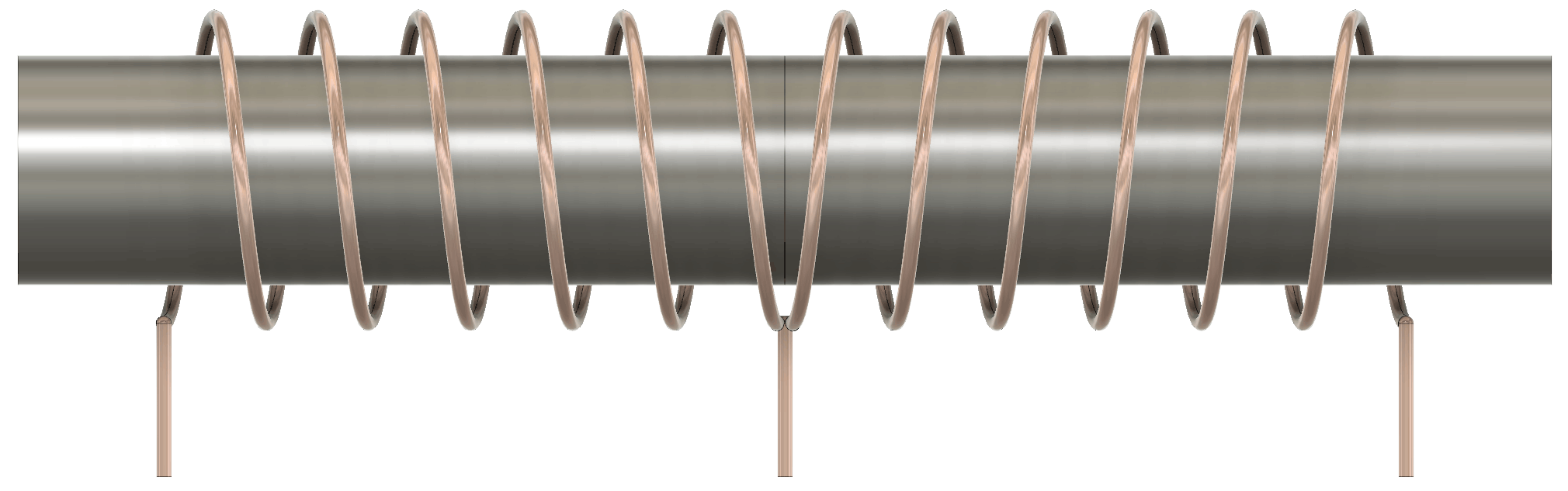
Efter några försök med att skala bred flatkabel tröttnade jag och tänkte ut ett annat sätt att åstadkomma samma sak. Med hjälp av en nyinskaffad 3D-skrivare skrev jag ut ett rör med ett spiralformat spår på utsidan där jag kunde linda en tunn oisolerad koppartråd (en kardel från en skalad, tunn kopplingstråd). På ena sidan av röret hade jag en skåra för att senare lätt kunna skära av trådarna längs skåran och på motstående sida en platt yta där jag först kunde limma en tunn strimla kopparlaminat för att löda fast trådvarven. Innan jag lödde och skar av trådarna på ovansidan säkrade jag det hela med superlim. Har man inte tillgång till 3D-skrivare borde det vara ganska lätt att uppnå samma sak med ett enkelt elrör. Se figurer 9-12.
Figur 9. 3D-modell av ”skärmformaren”. De runtgående spåren är spiralformade, som en gänga.Figur 10. Skärmformare med kopparlaminat på undersidan för jordning.Figur 11. Närbild på skärmformaren med tråd som lindats, limmats och kapats längs övre skåran.Figur 12. Komplett ferritantenn med skärm och trådar till de två lindningarna stickande ut i mitten.
Lindning av antennen
En mycket god idé som jag lånat från 80m12 är att låta själva lindningen runt ferritstaven bestå av två lindningar som båda börjar i mitten och går lika många varv ut mot varsin kant. Se figur 13. Lindningarnas ändar jordas medan man tar ut signalen på sammankopplingspunkten i mitten. Poängen med att ha två parallellkopplade spolar på detta sätt är att när man riktar ferritstaven mot sändaren och magnetfältet alltså går rakt in i bredsidan på ferritstaven så plockar den annars upp signal från ett varv och nollstället blir därmed förskjutet några grader med pejlfel som följd. De två parallellkopplade lindningarna ger motverkande signaler i detta fall och tar därmed ut varandra och eliminerar pejlfelet. Att ändarna är jordade bidrar till skärmningen mot E-fältet.
Figur 13. Ferritantennen lindas med två spolar som båda utgår från mitten. Ytterändarna jordas och signalen tas ut på mittledaren. Det är såklart mycket viktigt att lindningarna utgår åt samma håll (utåt ur bilden i denna illustration) från mittpunkten. Annars får man en kortsluten lindning när man jordar ändarna…
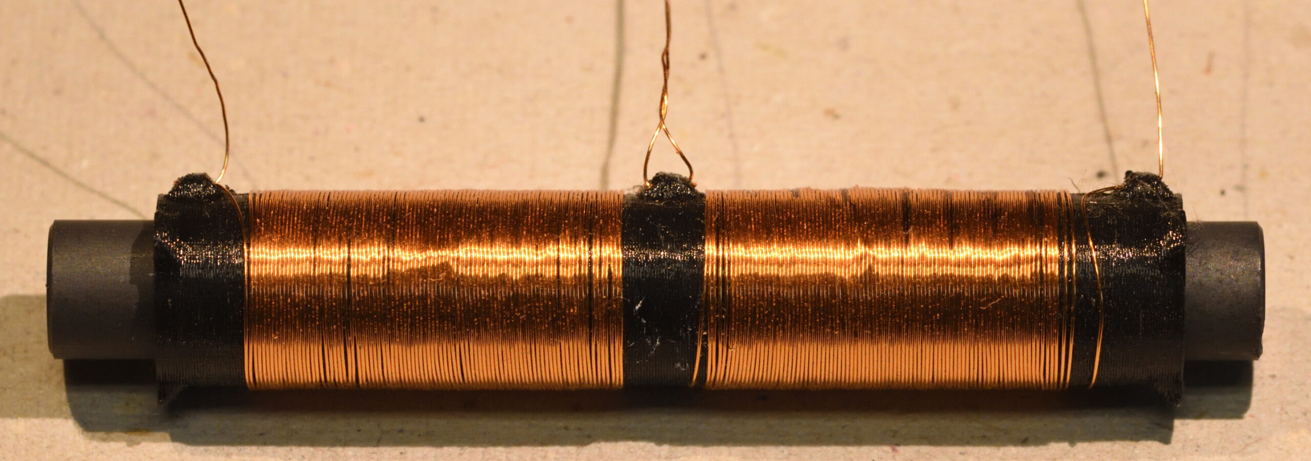
För att få så stark signal (hög spänning) som möjligt från antennen vill jag ha så många varv som möjligt utan att antennen blir resonant vid för låg frekvens. Därför är det viktigt att inte lindningarna får onödigt stor parasitkapacitans. Dielektricitetskonstanten för ferritmaterial är ganska hög, så att linda direkt på ferritstaven är inte optimalt. Istället skrev jag på 3D-skrivaren ut en spolformare som håller ferritstaven i mitten och låter koppartråden befinna sig någon mm ovanför ytan och håller det hela centrerat i skärmröret. Spolformaren har även hål som man kan låsa tråden i så att den inte lindar upp sig. Figur 14 visar spolformare med lindningar.
Figur 14. Spolformare och ferritkärna med lindningar. 80+80 varv med 0,25 mm lackad koppartråd.
Som ferritstav använde jag två hoplimmade stavar gjorda av material 61 från Fairrite. Stavarna har 9,5 mm diameter och längden 41 mm vardera. Fairrites artikelnummer är 4061375411 och den finns att köpa från Digi-Key under artikelnummer 1934-1575-ND.
Med antennen kopplad till ingången på mottagaren är resonansfrekvensen knappt 3 MHz. Det kan verka misslyckat att den inte är resonant på 3,5 eller 3,6 MHz, men eftersom jag vill jämföra fasen mellan ferritantennen och E-fältsantennen och få samma resultat oavsett var i bandet sändaren ligger så är min tanke att jag inte vill ha några stora skillnader i fas hos antennsignalen i det relevanta frekvensbandet och då duger det inte att ha en resonans i bandet. Det har visat sig möjligt att bygga en mottagare som inte kräver en resonant antenn för att ge bra mottagning, så principen verkar fungera utmärkt, även om det kan finnas ytterligare optimeringar att göra. Man skulle kunna utforska om det möjligen vore bättre att ta bort några varv och göra den resonant vid 4 eller 5 MHz, vilket är frekvenser som dämpas tidigt i RF-kedjan och därför inte utgör lika stor risk att orsaka blockering om det mot förmodan skulle finnas en stark signal på den resonanta frekvensen.
En massa bra information om dimensionering och optimering av ferritantenner (och loopantenner) hittade jag förresten i ett dokument som CIA tog fram på 50-talet och som numera finns tillgängligt för nedladdning. Se referens [2]. Mycket läsvärt för den tekniskt intresserade.
E-fältsantennen är okritisk och jag tog ca 7 cm 3D-filment, dvs en plasttråd med 1,75 mm diameter, och lindade några mycket glesa varv lackad kopparttråd på den samt satte en krympslang över. Det ger en antenn som tål att böjas och eftersom signalen visade sig vara starkare än från ferritantennen kan det knappast vara lönt att göra den längre.