Category Archives: CNC

Head lamp charging timer

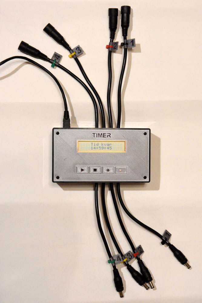
This article describes a simple timer that disconnects a number of lithium ion batteries from their chargers after a predetermined time. The timer consists of a Teensy LC (Arduino compatible) processor board, a 2×16 alphanumeric LCD, MOSFETs to connect/disconnect the chargers and batteries and a few 3D-printed parts.

The timer with connections for four chargers and batteries.

Why it is needed

The youth section of my local orienteering club has a few head lamps to lend out during trainings to kids who do not have their own. The batteries need to be charged after each use, but it might be several days or even weeks before the leaders are back at the club house to disconnect the batteries from the chargers. There are reports of accidents where the chargers or batteries have caught fire in situations like this, so it would be good if the charging time could be limited.

The first idea was to put a timer on the mains supply to the chargers. After a quick investigation, I noticed that the chargers actually consume current from the batteries when they are not plugged into mains (an LED on the chargers is even lit in this case), so this was not a good solution as the batteries would be empty after a week or two in this state.

Instead I decided to build a timer that interrupts the DC connection between the chargers and batteries rather than the mains supply to the chargers.

Circuitry

As the processor board I decided to use a Teensy LC board, which is a pretty small and inexpensive “Arduino compatible” board (i.e. it can be programmed in the Arduino environment) with an ARM Cortex-M0+ processor. It has 27 I/O pins, which is more than enough for this simple application. The Arduino/Teensy environment provides useful and time-saving libraries for controlling the alphanumeric LCD, doing switch debouncing and keeping track of the time.

As the user interface, I decided to use a 2×16 LCD together with four push buttons. The LCD can be used in either 8-bit or 4-bit mode and I opted for the 4-bit mode since it requires fewer wires to be soldered between the Teensy and the LCD. The LCD also needs a potentiometer to control the contrast. Without that, or with the wrong setting of the pot, it will probably not show any characters at all.

I connected four momentary closing push buttons between pins on the Teensy and GND. By enabling internal pull-ups on these pins, no resistors are needed – reducing the amount of soldering required.

All of the pieces described so far are mounted to the back of a 3D-printed front panel as shown in the photo below.

Back side of the front panel with push button board (top), Teensy floating above the LCD and a USB connector (bottom left).

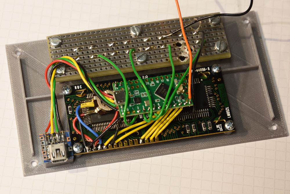
The USB signals are brought out to a separate mini-B connector mounted so that it is close to the side of the enclosure. The LCD is powered directly from the USB 5-V line. The 10-kohm potentiometer that provides the contrast signal to the LCD is connected between the LCD VCC pin (5 V) and GND. The push buttons are soldered to a scrap piece of perf board which is screwed to the front panel. Since the Teensy LC board is so small and lightweight, it works fine to just have it hanging in its short wires behind the LCD. An alternative would be to solder a few unused pins of the Teensy to the perf board.

The connection between the pieces are so few that they can rather easily be determined from the photo above. The code shown at the end of this post also defines which pins are used for what on the Teensy.

One pin of the Teensy controls the MOSFETs via the orange wire in the photo above. The MOSFETs are located on a separate piece of perf board, where most of the soldering in this project takes place:

The board with the six MOSFETs and associated circuitry.

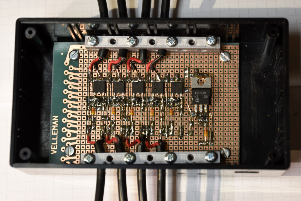
I used MOSFETs I had on hand, but unfortunately, I did not have six identical ones, so one of six channels is equipped with a different kind of transistor. The schematic for each of the channels is shown below:

Schematic of one channel.

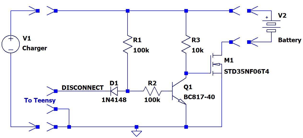
I did not want to control the MOSFET (M1) with the 3.3 V signal coming directly from the Teensy, since it might not turn on well enough with just 3.3 V. Instead I used a pull-up (R3) to the roughly 8-V voltage coming from the charger. When the NPN transistor Q1 is on, it pulls the gate of M1 low and thus turns it off and disconnects the battery from the charger. When the Teensy pulls the DISCONNECT signal low, the base current of Q1 (coming via R1) is diverted so that Q1 turns off and R3 can pull the gate of M1 high. Thus M1 turns on and connects the battery to the charger.

There is just a single DISCONNECT signal from the Teensy, connected to all the channels. The channels also share the same GND.

The Teensy is powered via a separate USB cable, so there could be a situation where the Teensy is unpowered, while there are chargers and batteries attached to the timer. I wanted the batteries to be disconnected from the chargers in this case and that is the reason for the diode D1. When the Teensy is unpowered, any of its pins will probably be about a diode drop (ESD diode) above GND if a small current is flowing into the pin. This might be a low enough voltage to prevent Q1 from turning on and M1 would be on, which I do not want. By adding the diode D1 in series with the DISCONNECT signal, we can be pretty sure Q1 will have enough base current to be on even when the Teensy is unpowered, and thus the batteries will be safely disconnected from the chargers in this case.

The MOSFETs I used (mostly STD35NF06T4) as M1 are vastly overkill in that they can handle much larger currents and much higher voltages than what will actually be needed here, so cheaper and smaller devices would work just as well. But I used what I had on hand that would fit the bill and I found no smaller suitable devices in the junk bin.

The processor connects to the MOSFET board with just a GND wire (black) and a DISCONNECT wire (orange).

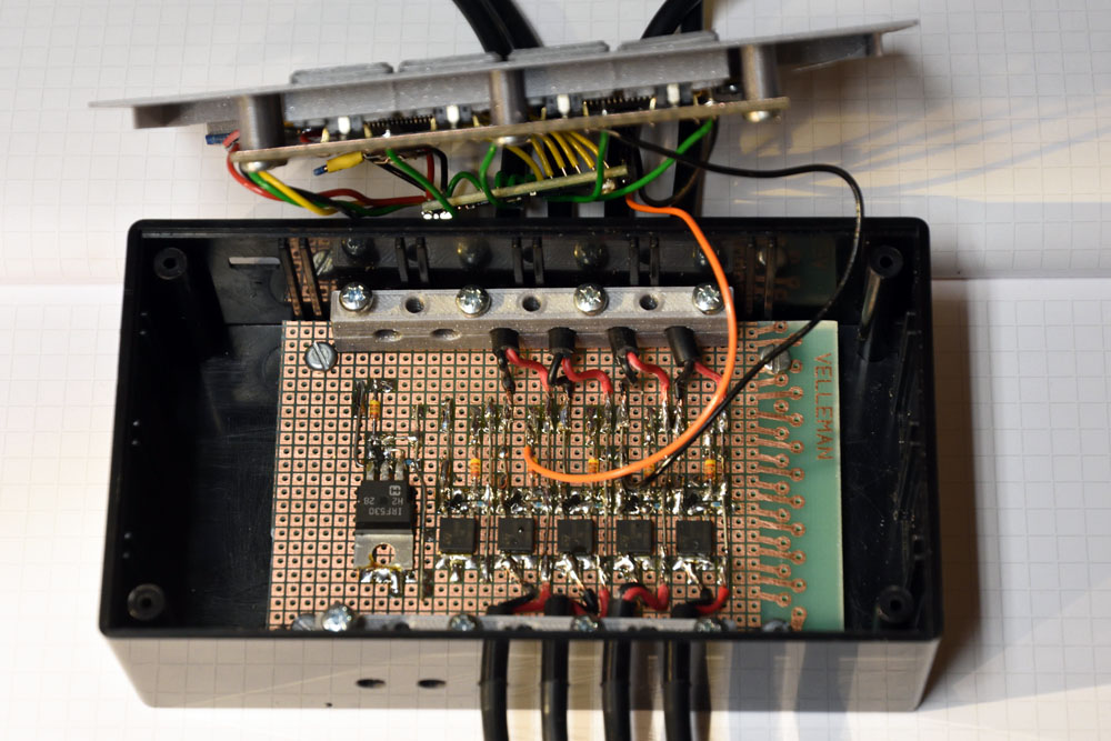
To connect the chargers and batteries to the timer, I used extension cords that were supplied with the headlamps, but which are not really needed when the lamps are used for running at night. I cut these cables in half and soldered them to the MOSFET board. Unfortunately only four such cables were available, so I will have to add two more in the future to enable channels five and six.

Mechanics

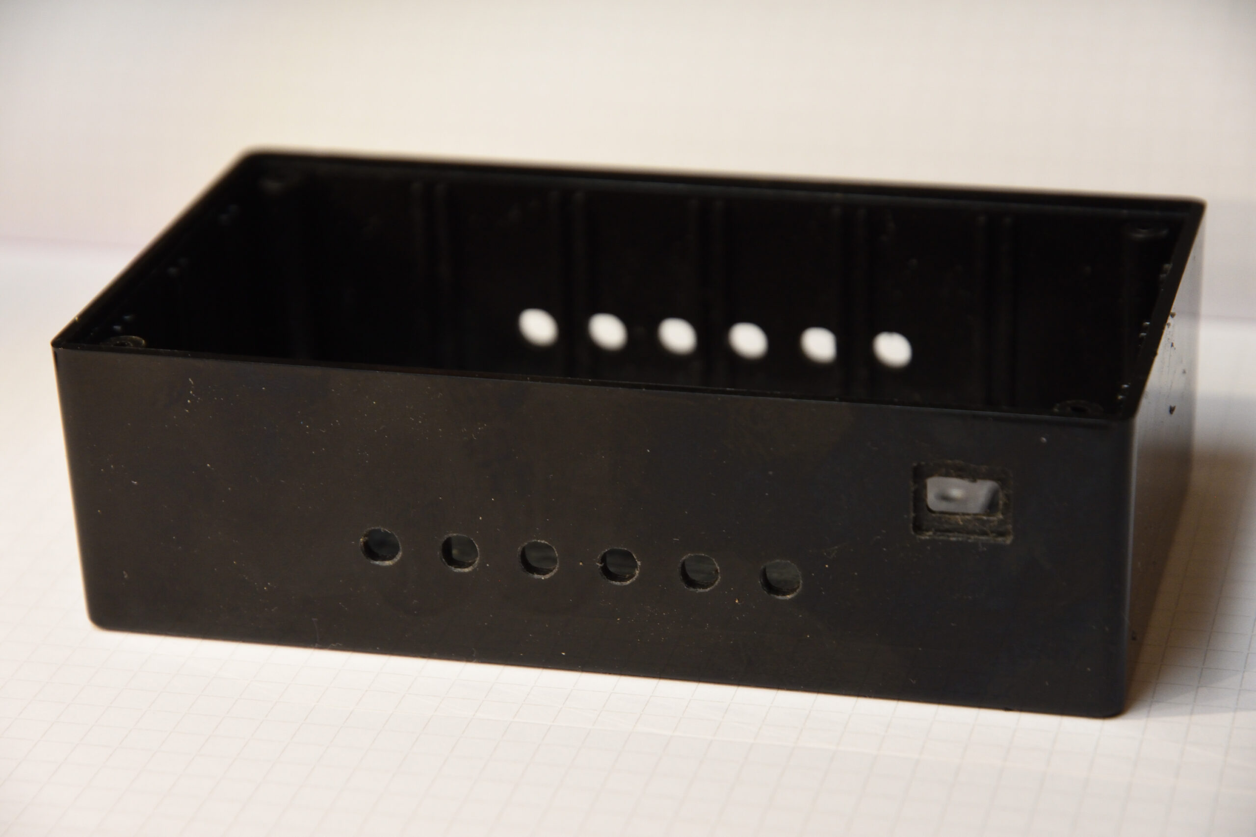
As the main part of the enclosure, I used a CU-1874-B box from Bud Industries, but as mentioned above, I replaced the lid with a custom 3D-printed part I designed in Fusion 360. It has screw posts for the display and for the board with the switches, as well as rectangular walled holes for 3D printed buttons that push on the switches. The front also has some reinforcements to make it more sturdy, although it gets pretty sturdy anyway when the LCD and the switch board have been screwed into it.

Back side of front panel.

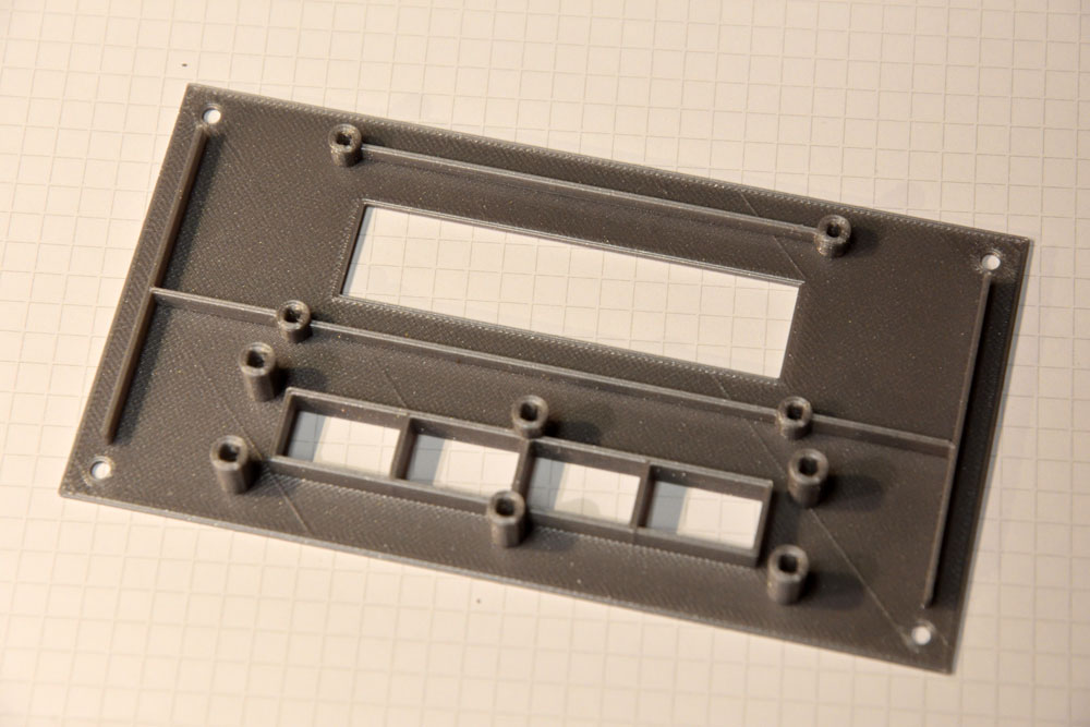
I designed the screw posts so that M2.5 (for the LCD) and M3 (for the switch board) screws could be self-threaded into them. The holes are square with sides of 2.1 mm for M2.5 and 2.6 mm for M3. The entrances of the holes are chamfered to make it easier to start the threads.

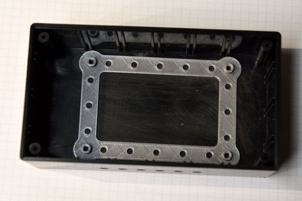
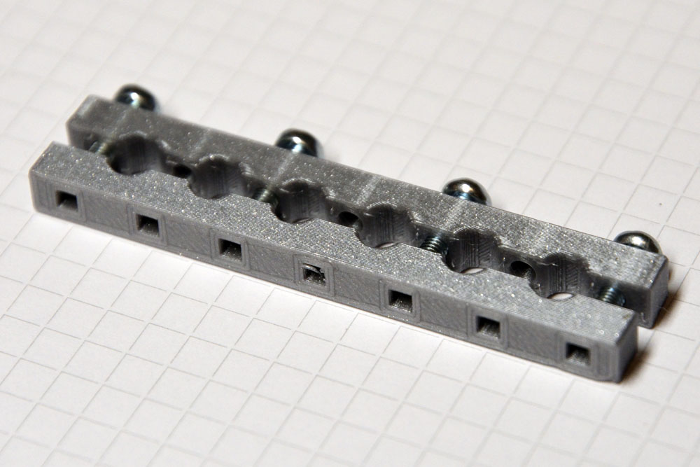
To mount the MOSFET board to the bottom of the box, I 3D-printed a frame (also with screw posts) that I then glued to the bottom of the box using CA glue. This way I did not have to drill any screw holes in either the front or the bottom of the box.

The frame for holding the MOSFET board.

I wanted to have proper strain reliefs on the cables and I 3D-printed those to fit all six cables at once. Again with square holes to allow M3 screws to self-tap into the material.

Strain relief for six cables.

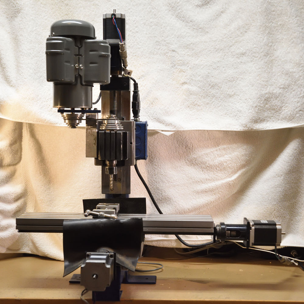
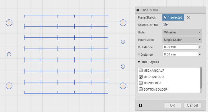
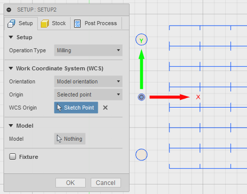
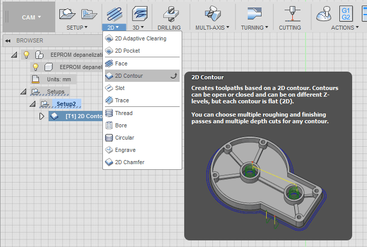
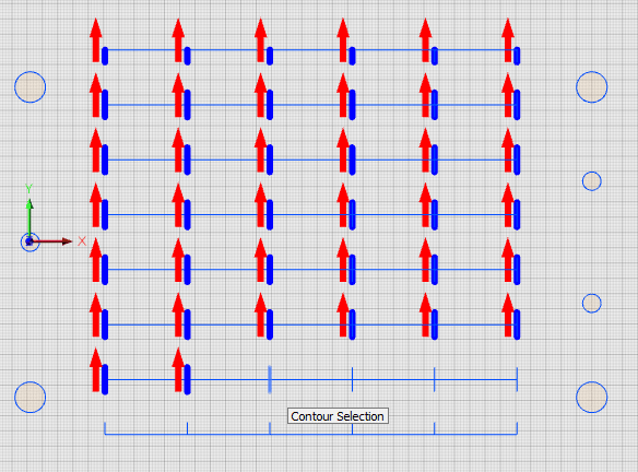
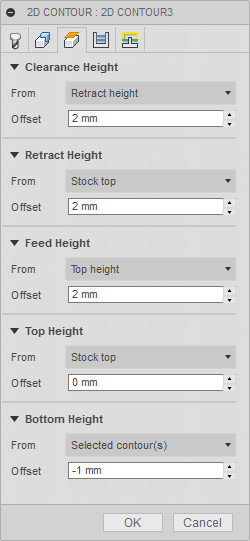
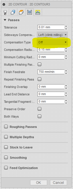
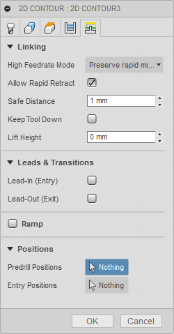
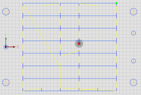
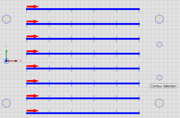
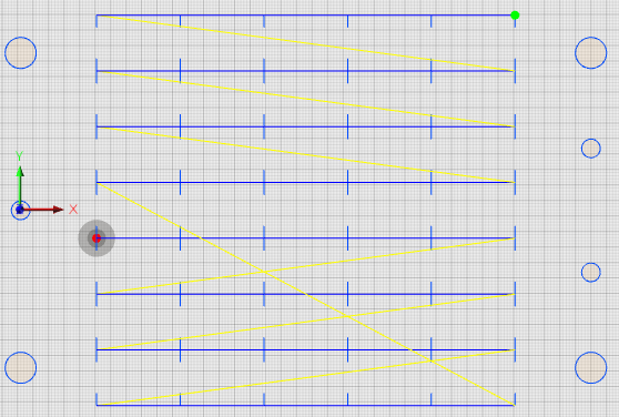
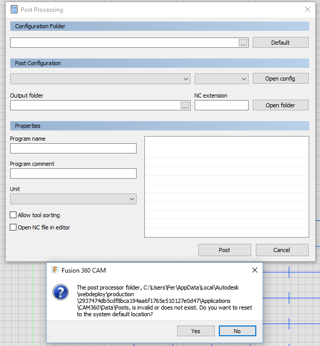
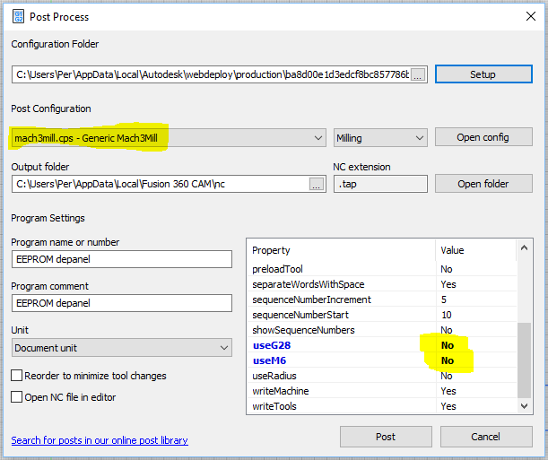
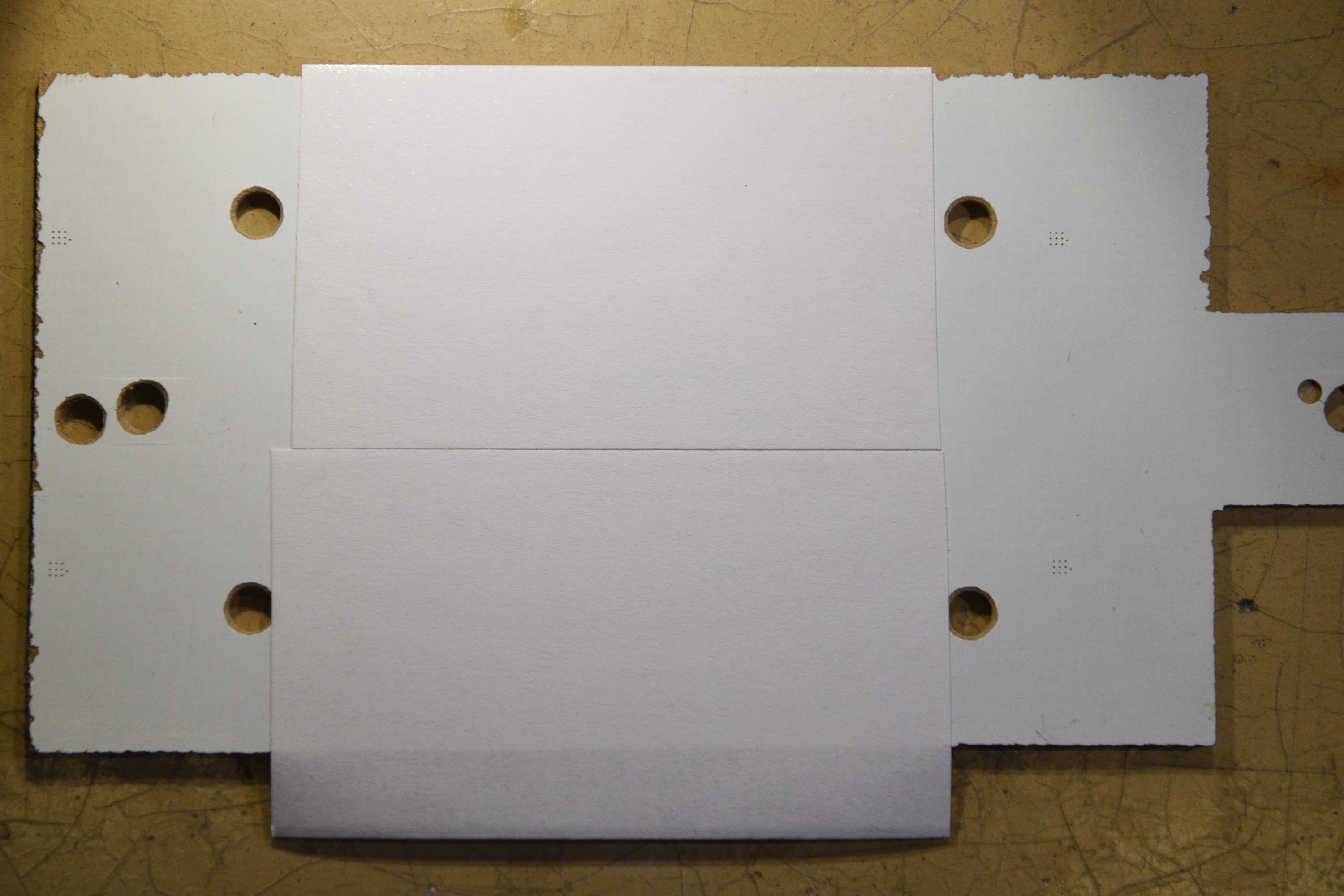
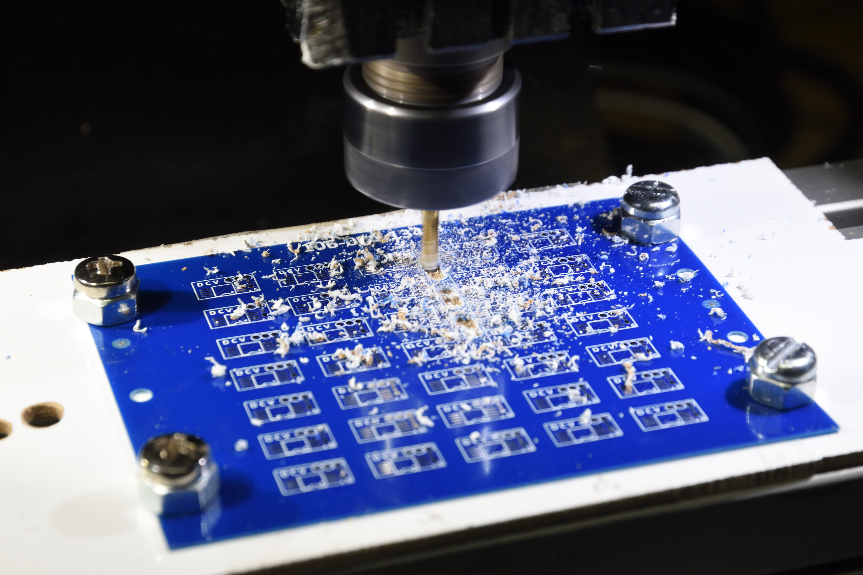
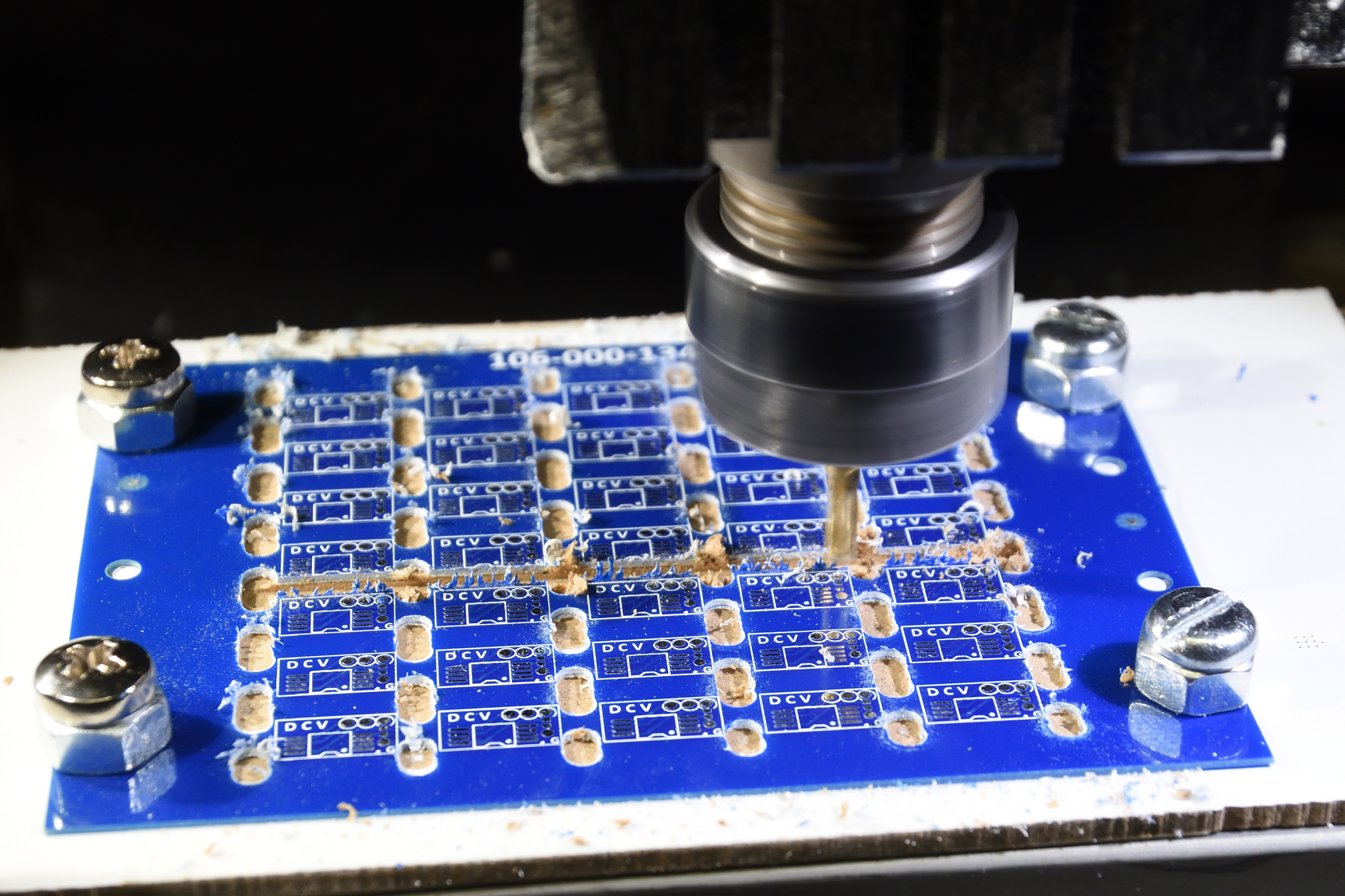
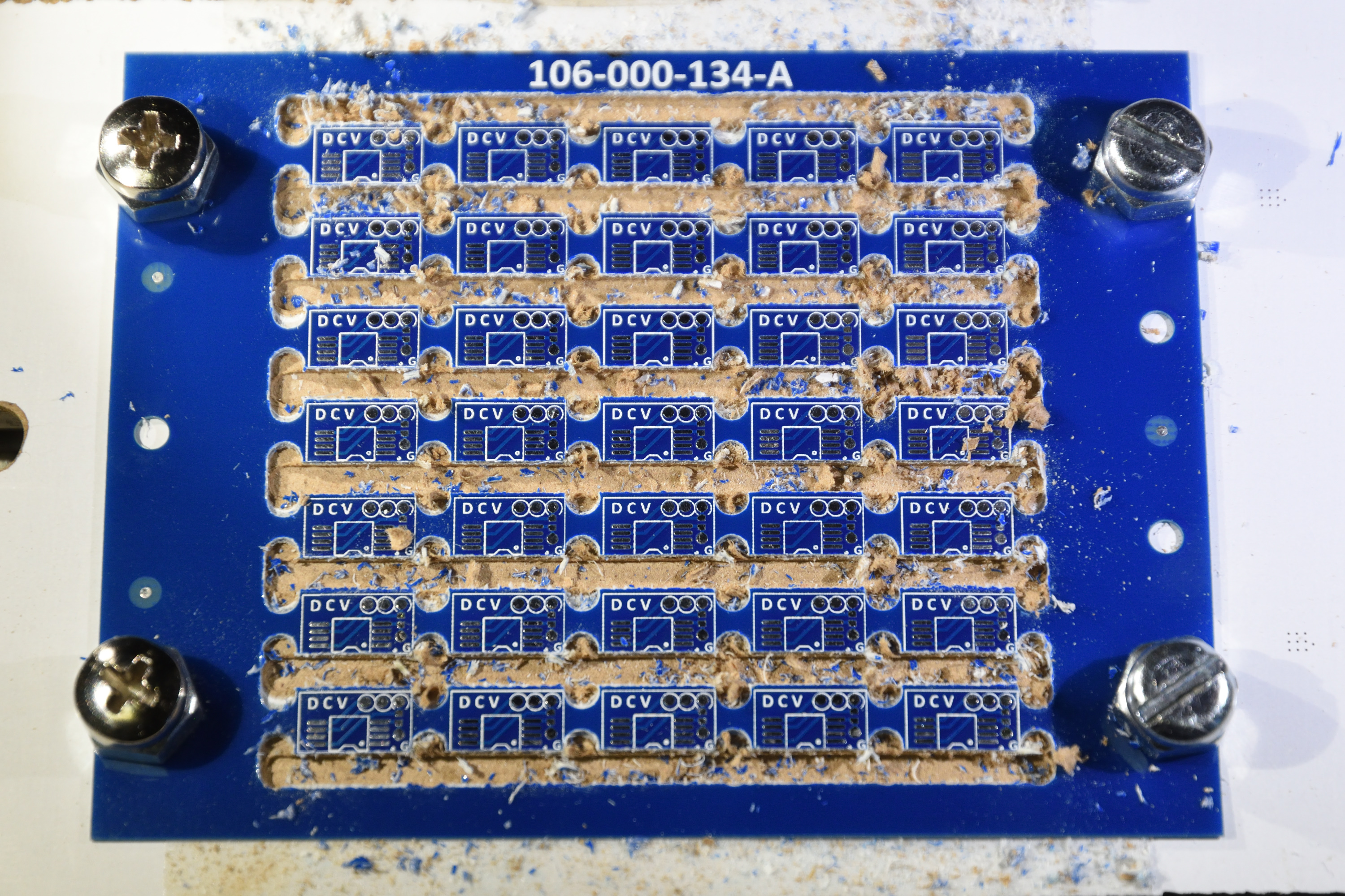
Even though no screw holes were needed in the box, there still had to be holes for the cables and for the USB connector to power (and if necessary reprogram) the Teensy. Since I have a CNC machine, I used that to mill these holes. The cable holes could easily have been made with simpler tools, but the wall around the USB hole had to be thinned for a proper fit of the connector and this was easier done with the CNC than with alternative methods.

The box with holes.

Code

The program running in the Teensy is a simple Arduino “sketch”. The LiquidCrystal library is used for communication with the LCD and the Bounce2 library is used for button debouncing. Time is kept by an elapsedMillis timer, a variable that automatically increments every millisecond.

The setup() routine – which is automatically called once at the beginning of an Arduino sketch – defines a custom LCD character (a right-arrow, play-symbol) used on the start screen to refer to the button to press to start the charging. It then sets up the I/O lines used for the four buttons; start, stop, increment and decrement. The line for the DISCONNECT pin and the on-board LED are set up as outputs.

The loop() routine is automatically called over and over again, indefinitely, in an Arduino sketch. In this case, it contains a simple state machine that keeps track of whether the timer is running or if it is stopped. If it is stopped, it only reacts to the start (or “play” if you will) button. By default, it starts a 15 hour countdown when play is pressed.

If instead the timer is already running, it will react to either increment, decrement or stop. Stop is self explanatory, while increment and decrement increase or decrease the remaining time. Initially the steps are 1 hour, but when the remaining time is lower, the steps are reduced accordingly. A maximum time of 48 hours have been defined earlier in the program.

When the timer is running, the LCD shows the remaining time in the format HH:MM:SS and this is updated every second. The LED is also toggled every second, although this will not be visible to the user as it is embedded deep in the opaque box.

Finally the program contains a few functions to help with showing information on the LCD.

Here is the complete code:

/* Head lamp charge timer.

   Disconnects a charger from a (head lamp) (LiIon) battery after a given time
   to reduce the risks of having a charger connected for a long time to 
   a LiIon battery.

   The user interface consists of a 2x16 LCD panel and some buttons.

   Target: Teensy LC
   
   Written by Per Magnusson, http://www.axotron.se
   v 1.0 2021-01-08
   This program is public domain.
*/

#include <Arduino.h>
#include <LiquidCrystal.h>
#include <Bounce2.h>

static const int32_t DEFAULT_TIME = 15*60*60*1000; // In milliseconds
static const int32_t MAX_TIME     = 48*60*60*1000; // In milliseconds
static const int32_t TIME_STEP    =  1*60*60*1000; // In milliseconds
static const int32_t TIME_STEP2   =    10*60*1000; // In milliseconds
static const int32_t TIME_STEP3   =     1*60*1000; // In milliseconds
static const int32_t TIME_STEP4   =       10*1000; // In milliseconds


// Stated
static const int32_t STATE_OFF = 0; // Not charging
static const int32_t STATE_ON  = 1; // Charging


// Pins
static const int START_PIN = 2;       // Start timer (and turn charging on)
static const int STOP_PIN = 3;        // Stop timer (and turn charging off)
static const int INC_PIN = 4;         // Increment timer by 1 hour
static const int DEC_PIN = 5;         // Decrement timer by 1 hour
static const int DISCONNECT_PIN = 12; // High disconnects charger from battery

// LCD           RS  E D4 D5  D6  D7
LiquidCrystal lcd(6, 7, 8, 9, 10, 11);

static const int LED_PIN = 13;

elapsedMillis timer;
uint32_t end_time;
int32_t state;

Bounce b_start = Bounce();
Bounce b_stop = Bounce();
Bounce b_inc = Bounce();
Bounce b_dec = Bounce();

// Custom character
byte play_glyph[] = {
  B00000,
  B10000,
  B11000,
  B11100,
  B11110,
  B11100,
  B11000,
  B10000
};
const byte play_char = 0;


void setup() 
{
  Serial.begin(57600);
  lcd.begin(16, 2);
  lcd.createChar(play_char, play_glyph);
  
  b_start.attach(START_PIN, INPUT_PULLUP);
  b_stop.attach(STOP_PIN, INPUT_PULLUP);
  b_inc.attach(INC_PIN, INPUT_PULLUP);
  b_dec.attach(DEC_PIN, INPUT_PULLUP);
  b_start.interval(25);
  b_stop.interval(25);
  b_inc.interval(25);
  b_dec.interval(25);

  timer = 0;
  end_time = 0;
  state = STATE_OFF;

  pinMode(DISCONNECT_PIN, OUTPUT);
  digitalWrite(DISCONNECT_PIN, HIGH);

  pinMode(LED_PIN, OUTPUT);
  digitalWrite(LED_PIN, HIGH);
  lcd_splash();
  digitalWrite(LED_PIN, LOW);
  Serial.println("Charge timer");
}


void loop() 
{
  static uint32_t last_update = 0; // The last time the display was updated

  b_start.update();
  b_stop.update();
  b_inc.update();
  b_dec.update();
  
  if(state == STATE_OFF) {
    // Timer is off
    if(b_start.fell()) {
      // Start timer
      timer = 0;
      end_time = DEFAULT_TIME;
      state = STATE_ON;
      digitalWrite(DISCONNECT_PIN, LOW);
      digitalWrite(LED_PIN, LOW);
      lcd_update();
      last_update = 0;
    }
  } else {
    // Timer is on
    if(timer > end_time) {
      // Time has run out
      state = STATE_OFF;
      digitalWrite(DISCONNECT_PIN, HIGH);
      lcd_done();
    } else if(b_stop.fell()) {
      // The stop button was pressed
      state = STATE_OFF;
      digitalWrite(DISCONNECT_PIN, HIGH);
      lcd_stop();
    } else if(b_inc.fell()) {
      // Increment time
      if(end_time - timer < TIME_STEP3) {
        end_time += TIME_STEP4;
      } else if(end_time - timer < TIME_STEP2) {
        end_time += TIME_STEP3;
      } else if(end_time - timer < TIME_STEP) {
        end_time += TIME_STEP2;
      } else {
        end_time += TIME_STEP;
      }
      if(end_time > MAX_TIME) {
	      end_time = MAX_TIME;
        timer = 0;
        last_update = 0;
      }
      lcd_update();
    } else if(b_dec.fell()) {
      // Decrement time
      if(end_time - timer < TIME_STEP3 + 3 * TIME_STEP4) {
        end_time -= TIME_STEP4;
      } else if(end_time - timer < TIME_STEP2 + 5 * TIME_STEP3) {
        end_time -= TIME_STEP3;
      } else if(end_time - timer < TIME_STEP + 3 * TIME_STEP2) {
        end_time -= TIME_STEP2;
      } else {
        end_time -= TIME_STEP;
      }
      lcd_update();
    }
    if((state == STATE_ON) && (timer > last_update + 1000)) {
      lcd_update();
      last_update = (timer / 1000) * 1000;
      if(digitalRead(LED_PIN)) {
        digitalWrite(LED_PIN, LOW);
      } else {
        digitalWrite(LED_PIN, HIGH);
      }
    }
  }
}


// Draw the splash screen
void lcd_splash()
{
  lcd.clear();
  lcd.noCursor();
  lcd.noBlink();
  lcd.setCursor(0, 0);
  //         0123456789012345
  lcd.print(" Laddningstimer "); // Charging timer
  lcd.setCursor(0, 3);
  //         0123456789012345
  lcd.print("    Tryck "); // Press
  lcd.write(play_char);    // >
}


// Draw the screen showing that charging has finished
void lcd_done()
{
  lcd.clear();
  lcd.noCursor();
  lcd.noBlink();
  lcd.setCursor(0, 0);
  //         0123456789012345
  lcd.print("    Laddning    "); // Charging
  lcd.setCursor(0, 3);
  //         0123456789012345
  lcd.print("      klar      "); // done
}

// Draw the screen showing that charging has finished
void lcd_stop()
{
  lcd.clear();
  lcd.noCursor();
  lcd.noBlink();
  lcd.setCursor(0, 0);
  //         0123456789012345
  lcd.print("    Laddning    "); // Charging
  lcd.setCursor(0, 3);
  //         0123456789012345
  lcd.print("    avbruten    "); // interrupted
}

// Convert a positive number between 0 and 99 to a nul-terminated
// string with two digits. The first character is 0 for numbers below 10.
void int_to_00str(uint32_t num, char *str) {
  str[2] = '\0';
  str[1] = (num % 10) + '0';
  str[0] = (num - (num % 10))/10 + '0';
}


// Convert a positive number between 0 and 999 to a nul-terminated
// string with three digits. Leading zeros are replaced by spaces.
void int_to_3str(uint32_t num, char *str) {
  str[3] = '\0';
  str[2] = (num % 10) + '0';
  num -= (num%10);
  num /= 10;

  str[1] = ' ';
  if(num > 0) {
    str[1] = (num % 10) + '0';
    num -= (num%10);
    num /= 10;
  }

  str[0] = ' ';
  if(num > 0) {
    str[0] = (num % 10) + '0';
  }
}

// Update the countdown timer on the LCD
void lcd_update()
{
  uint32_t time_left;
  uint32_t seconds;
  uint32_t minutes;
  uint32_t hours;
  char sec_str[3];
  char min_str[3];
  char hour_str[4];

  time_left = end_time - timer; // ms
  if(time_left < 0) {
    time_left = 0;
  }
  time_left /= 1000; // s
  seconds = time_left % 60;
  time_left -= seconds;
  time_left /= 60; // minutes
  minutes = time_left % 60;
  time_left -= minutes;
  time_left /= 60; // hours
  hours = time_left;
  
  int_to_00str(seconds, sec_str);
  int_to_00str(minutes, min_str);
  int_to_3str(hours, hour_str);

  lcd.setCursor(0, 0);
  //         0123456789012345
  lcd.print("    Tid kvar    ");
  lcd.setCursor(0, 1);
  //         01234567890123456789
  lcd.print("   ");
  lcd.print(hour_str);
  lcd.print(":");
  lcd.print(min_str);
  lcd.print(":");
  lcd.print(sec_str);
  lcd.print("    ");
}

Changing Spindle Bearings on a Taig CNC Mill

The spindle on my Taig CNC mill was getting uncomfortably hot after a few minutes of milling; especially at higher RPMs. It ran smoothly and without any play, but with noticeable friction, so I decided to try to change the ball bearings.

Taig CNC mill

Ball Bearing Selection

The bearings have the standard dimensions 17x40x12 mm (inner diameter x outer diameter x width) and this apparently is designated with the number 6203 in the ball bearing world.

I am not a mechanical engineer and have little knowledge of the intricacies of ball bearings and it was also surprisingly hard to find a lot of good information online on how to select the proper bearings for the application. I wanted high quality to avoid having to change them soon again and I thought that dust covers would be a good idea to minimize the risk of chips getting into particularly the lower bearing. After some browsing of an online catalog (at kullagret.com, although there are countless others), I realized that there were plenty of options, even after selecting a particular well respected brand. It was clear that deep groove bearings were required since they can handle axial loads as well as radial ones. Since rubber seals were slightly more expensive than metal shields, I thought they were superior and bought two SKF 6203-2RS bearings. This unfortunately turned out to be less than ideal.

After replacing the bearings (the process I used is described below), it turned out that the spindle still rotated with quite a bit of friction. The rubber sealed bearings themselves did indeed have significant friction, which was concerning even before putting them into the spindle, but it became even worse after the assembly was done. A quick test run revealed that the spindle got at least as hot as before and that the motor was almost not powerful enough to even run the unloaded spindle at full speed at the highest gear.

I  think part of the reason for the high friction was the rubber seals, but since it got even worse after assembly, I think there is also another part of it. It must be either that the bearings  are put under radial stress in the spindle, compressing them tighter and thus causing them to run with higher friction, and/or that there is ever so little misalignment  between the two bearings.

So, back to the bearing catalog. This time I tried to address both of the reasons for the high friction. I opted for bearings with a higher play, designated by the option C3. I also selected an unshielded bearing for the top one (6203/C3) – which will hopefully not be subjected to chips or other debris – and metal shields for the lower bearing (6203-2Z/C3). This worked much better and now the spindle runs smoothly with very little friction and no discernible play.

Below is a description of how I replaced the bearings the second time.

Disassembly

I first removed the spindle motor. It is fastened only by two screws holding its mounting plate to the rest of the spindle.

The spindle is secured to the Z-axis assembly by a single set screw holding on to a dove tail, so this was easy to remove.

Spindle removed from mill

The pulley is secured by two set screws. I released them and gently applied some force to pull it off from the shaft. There probably are some good special tools for this, but I used two screwdrivers as levers.

Removing the pulley

Under the pulley, there is a nut (with a very fine thread) that needs to be removed. I held on to the shaft by one wrench on the lower side while using another to loosen the nut.

Removing the nut

Now the shaft had to be pushed out of the bearings. This takes a lot of force. Maybe there is some trick that I am not aware of. Using a mallet to hammer it out might be one option, but I initially tried to be more gentle by using clamps (more than one was required to two get enough force) together with wooden blocks to avoid damaging the shaft. If I had had a gigantic vise with a wide enough mouth, that would probably have been a better option.

Pushing out the shaft using clamps and wooden blocks

Once the shaft was fully pushed into the top bearing, I resorted to hammering on a dowel at the end of it.

Hammering out the shaft using a dowel

This was successful.

The shaft has successfully been removed.

The next step was to remove the bearings. Here I came up with an (in my opinion) clever method. The housing is made of aluminum and the bearings are obviously made of steel. Aluminum expands a little more when it is heated than what steel does, so by heating the whole thing up by a few tens of degrees, it should be much easier to remove the bearings. So I set the kitchen oven to 60 C and let the spindle cook for an hour or so.

Cooking the spindle

This was even more effective than I had thought. The bearings more or less fell out by themselves.

Bearings falling out of hot spindle.

There were a few shims between the ends of the bearings and the spindle, probably to prevent the inner ring of the bearings to touch any part of the housing.

Re-assembly

Before the housing cooled down, I inserted the new bearings into it (together with the  shims).

Upper bearing without shield or seal

Lower bearing with metal shield

Inserting the shaft into the new bearings was a bit hard. I probably should have heated up the new bearings before attempting this. Instead I lubricated the shaft a little (not sure this helped) and used force in the form of a hammer to hammer it in. Maybe this could harm the bearings due to the high axial load, but fortunately the spindle ran fine afterwards, so perhaps it was no big deal. Next time I will probably heat the bearings (and perhaps even cool the shaft, although I am worried that might cause too much condensation and then rust) before trying to force it in.

Hammering in the shaft

After making sure the shaft turned smoothly with little friction and with no discernible play, I replaced the nut (not tightening it very hard as that increased friction), added the pulley and then put the whole thing back onto the mill.

The shaft and its nut are back

Reassembled Taig CNC mill

So despite the unnecessary set of sealed bearings I bought and having to do it all twice, I am pretty happy with the bearing replacement. Now the mill runs fine without the spindle getting hot, even after long runs at maximum RPM.

Another try at PCB depanelization

I tried to separate the PCBs on another panel using the CNC mill. Here is the report on how I did it (so that I remember until next time).

The PCB panel

The first step is to have a CAD drawing in DXF format of at least where the center lines of all the cuts shall go. It is not obvious how to best lay out these lines. Should one go for fully separated PCBs? Or should one leave bridges between them to avoid the problem of PCBs (maybe) flying around as soon as they are separated, but with the problem of not getting fully separated PCBs in the end?

This time the PCBs were super-small, only 10.5 mm x 6 mm, so I decided that the holding force of the double sided tape would probably not be strong enough to securely keep the PCBs in place. Therefore I opted for only partial depanelization by milling. Since the thickness of the PCBs in this case was only 0.6 mm, I could use scissors for the final step. In fact, I could have exclusively used scissors and not involved the mill at all, but that would not be as fun. And one could argue that that would have resulted in more warping and strain on the PCBs.

To define the mill pattern, I exported data in DWG format from the CAD program (Altium) and opened it in DraftSight where I made some adjustments. After this, the CAD files contained the center lines of the mills, the board outline and the outlines of the holes in the panel. I then saved it as a DXF-file, as Fusion 360 (where I create the G-code program for the mill) does not seem to understand DWG.

In Fusion 360, I started a new sketch and used the command INSERT -> Insert DXF to import the CAD file.

DXF import dialog in Fusion 360.

Here one can select which layers to import and what units to use. In my case I only needed the data on layer MECHANICAL8 and the units were (of course) millimeters.

When the data is in, one does not have to do any more work in the MODEL section of Fusion 360, but there is more to be done in the CAM section.

Add a new setup (SETUP->New Setup) and make appropriate selections. One important thing is to define the origin in a clever position that is easy to identify and calibrate on the mill. For this purpose I had placed a 3 mm hole in the panel which I intended to locate using the 3 mm end mill needed for the depanelization (2 mm would probably have been a better idea, but I do not currently have a suitable 2 mm end mill). For some reason, Fusion 360 refused to select the center of the 3 mm circle as the origin until I first placed the origin at the end of a mill line and then retried to select the circle. Weird bug.

Defining the origin as a Sketch Point

In the Stock tab of SETUP I selected Relative size box, No additional stock and Round Up to Nearest 1 mm. This is probably unimportant since there is not even any 3D body defined, so Fusion 360 thinks the model has zero size.

In the Post Process tab, I added a suitable Program Name and Program Comment (helps with default file name and comments in the G-code).

The main trick is to use 2D contour with Compensation Type set to Off as the milling strategy in order to let the center of the mill follow the center of the lines in the drawing. This is done by 2D->2D Contour:

Adding a 2D contour milling pass

I selected the appropriate tool in the first tab (in this case a 3 mm end mill) and in the second tab I selected all the vertical segments. This is a bit tedious since drag-select does not work. The reason I only selected these segments and not the horizontal ones, is that I want the panel to stay as rigid as possible as long as possible:

Selecting all the vertical segments in the first 2D contour pass (not all segments have yet been selected above).

In the third tab, I define the heights. I generally decrease the clearance and retract heights to make the machining faster. I let the Top Height be 0 mm from Stock top and set the Bottom Height to -1 mm from the Selected contour(s) (Stock top would also have worked). This defines that the tool will go 1 mm deep (when I zero the mill on the top of the PCB), which is enough since the PCB panel is 0.6 mm thick.

Defining heights

The fourth tab is very important. This is where Compensation Type shall be set to Off so that the center of the mill tool is not offset from the lines:

Set Compensation Type to Off.

The fifth and final tab is also somewhat important. Here we need to untick the Lead-In and Lead-Out boxes to avoid undesired lateral movements of the mill that would ruin the PCBs. I also unticked the ramp box and let the tool plunge straight down:

Untick Lead-In and Lead-Out.

After clicking OK, the following tool path (yellow) was generated:

First tool path, vertical cuts

Fusion 360 reorders the segments in some more or less optimal order. The order in which the segments were selected does not seem to matter.

Duplicate the operation (to avoid a lot of repetition of settings), clear which segments are selected and select the horizontal lines:

Selection of horizontal segments

The resulting tool path looks like this:

Tool path for horizontal segments

As I mentioned, the reason for having two operations is that I wanted to mill the short segments first (to keep the panel as rigid as possible as long as possible) and with a single setup, it is impossible to control the order of the milling.

To generate the G-code, click on the Setup containing the two milling operations (so that not just one of the milling steps is selected) and then select ACTIONS->Post Process.

Fusion 360 has an irritating habit of forgetting the post processing settings when it updates itself. This results in the following error message:

Stupid post processing error message after Fusion 360 has updated itself.

Since the previous configuration has been forgotten, I have to tell it again that I do indeed have a Mach 3 mill and (very importantly) that it should not use the commands G28 and M6.

Important settings for my mill.

After the G-code has been generated (by clicking Post), it is finally time to set up the mill to do the work. I had designed the panel such that it had four 5 mm holes that fit with the T-slots of the milling table. I drilled corresponding holes in a piece of sacrificial MDF board and placed double sided tape on the board:

MDF with holes matching the panel and double sided tape.

I then put down the PCB panel on the tape:

The PCB panel has been attached to the MDF board.

It is then time to screw the panel to the table while making sure the panel edge is very parallel to the table. I had to use oversize (M6) nuts under the heads of the screws to make them fit with the T slots:

Panel in the mill.

I manually moved the mill precisely to the 3 mm hole on the left edge of the panel and zeroed the coordinates. Then it was time for action:

Milling the vertical slots.

Milling the horizontal slots.

Milling finished!

Using a pair of scissors, I cut the PCBs apart.

Individual PCBs

The result is acceptable, but not perfect. There are some burrs, which may have been caused by the end mill not being as sharp as it should have been. At first glance there seems to be a bit of mis-registration of the milling compared to the PCBs, but at least some part of  this is actually mis-registration between the overlay print and the copper. Compared to the copper, the milling seems to be very well positioned.

An idea for future improvement that I have is to not just leave a bridge between boards, but make this bridge thinner by milling down partially through the laminate. Maybe one can get away with leaving 0.3 mm or so of the material. This would make the scissor cutting easier. It is probably best to make these partial depth mill cuts first when the tape is pristine and let the full depth cuts (which can tear the PCBs somewhat loose from the tape) follow later.