Monthly Archives: September 2013

Making a time-lapse video

The previous post was about building the hardware for a remote release timer, programming it and capturing a (large) number of JPEG files. This post is about going from there to creating a video.

Making a video

So here comes the part that was most difficult for me and where I had to learn a couple of new things. I have hardly worked at all with video before and turned to Google to figure out how I could accomplish some results without buying expensive commercial software. After all, this is just a minor hobby project.

After some iterations, these are the steps I went through to produce a video:

  1. Crop the images to 16:9 format (and also scale them down to 1920×1080).
  2. Assemble and code the images into an MPEG 4/H.264 file at 30 fps.
  3. Find some suitable free music to use as soundtrack.
  4. (Edit the music to fit the length of the video.)
  5. Add some title text before the main video and some more text after it.
  6. Publish it all on Youtube.

Here is how I did it on a computer running Windows 7:

Cropping and rescaling

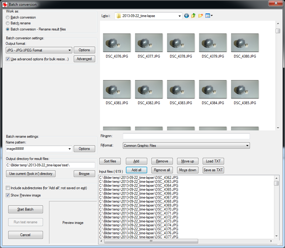
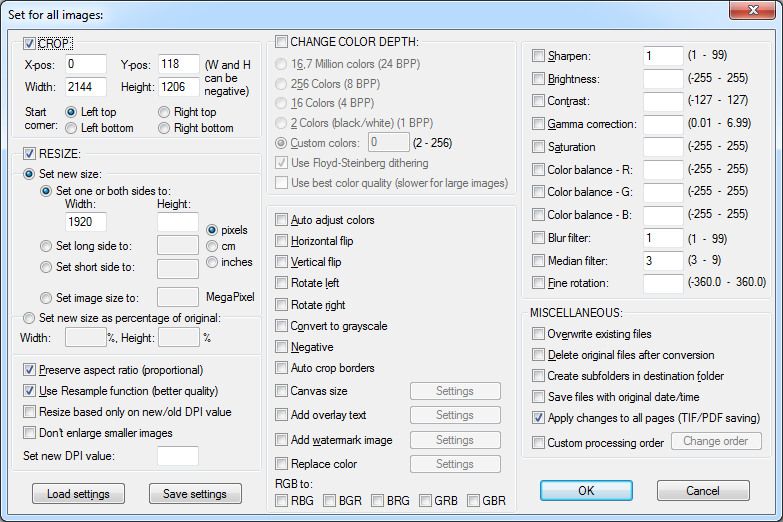
I had the excellent free (image) viewer Irfanview already installed and it turns out that it is the perfect tool for batch cropping and rescaling of photos. I found this tutorial that explains how to do it, but basically you just select File -> Batch Conversion/Rename, add the files you want to crop, click “Advanced batch conversion settings” and set up all the relevant parameters there. See screenshots below.

I had to crop from 2144×1424 to 2144×1206 (to get the 16:9 aspect ratio) and then I also let Irfanview rescale to 1920×1080 and place the resulting files in a subdirectory.

Batch processing dialog in Irfanview. Select files here and click on Advanced to set up the cropping and scaling.
Advanced batch processing options in Irfanview.
Images to video

I found a wonderfully unbloated and straightforward – yet functional – tool to do the conversion from JPEGs to an mp4 video, namely “Images to video“. The program needs no installation and has a single window (it can also be used from the command line). Below is a screenshot of it.

The only window in the program "Images to video"
The only window in the program “Images to video”

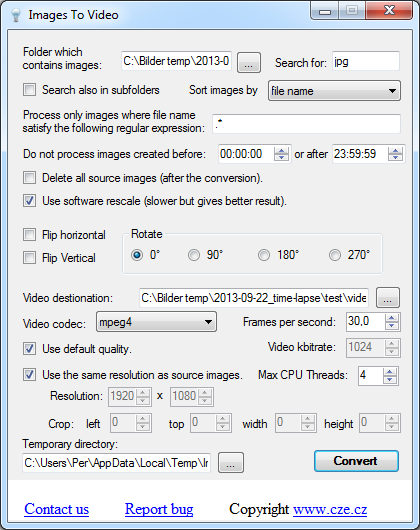
After setting up this dialog, you just press Convert and after a (relatively short) while, a video file pops out. Since the cropping and scaling was done using Irfanview we do not have to worry about it here, which is good since I could not figure out how the cropping features here worked. As soon as I set any of the crop values to higher than 0, the resulting video file came out empty.

Soundtrack

A video is more interesting to view if it has some sound. It turns out that there exists quite a bit of music released under a Creative Commons license. This page has a list of links to various sites with royalty free music. I found what I was looking for at incompetech.com, where Kevin MacLeod has published a large number of tunes. You just need to credit him appropriately if you use the music.

Edit the music

You may or may not need to edit the music. If you want to e.g. cut out a part of a tune and have detailed control over fade it in and fade out, Audacity seems like a good choice. I used this at first, but the options in Windows Movie Maker (see next section) turned out to be enough for my humble needs at this point.

Bringing it all together

To compose a video with a title screen, some information after the actual video and a soundtrack, I used Microsoft’s Movie Maker that you can download for free. The program does not give you a lot of control, but it is straightforward to use and was good enough for this project.

Putting it on Youtube

This part is very easy. Just create a Youtube account unless you already have one and upload the video.

The results

So, what did become of all this? Below are some of the crude results of my efforts as a fledgling time-lapse video creator.

Magnetic putty devouring a magnet

Magnetic putty sneaking up on a magnet.


Time-lapse shutter release based on Arduino

Combining electronics and photography can be quite fun. Here is a description of a mini-project I did recently.

I have some magnetic putty that I wanted to take time lapse video of. I also have a digital still camera (Nikon D300) and a manual remote shutter release with 2.5 mm stereo jack connectors. There are remote shutter releases with time-lapse functionality built in, but this was not present on mine, so instead I decided to create the time-lapse functionality by means of an Arduino Nano. (After almost completing this post, I realized that there is in fact a shutter release timer feature in the D300 menus. Duh! So I could have used that if I had settled for having the same time between each pair of exposures.)

Interfacing to the camera is quite simple. Two open collector outputs are needed, one for pressing the shutter release button halfway (to focus) and one for pressing it all the way down to take the picture. Some experimentation showed that it is necessary to first emulate pressing the button halfway and then release the shutter. It did not work if the halfway step was skipped.

It would probably be possible to use Arduino pins directly to talk to the camera by switching the pins between tri-state (button not pressed) and low (button pressed), but I decided to use external transistors to ground the signals instead as shown in the schematic below.

Shutter release schematic
Circuit for interfacing an Arduino to the shutter release cable.

The signals Release and Focus go to Arduino pins.

In addition to the camera control signals, I added a power MOSFET connected to another Arduino pin in order to control LED lighting. This might be useful when the period between pictures is very long to save power and prevent the LED from getting unnecessarily hot. In the end I did not use this feature as I suspect it might contribute to somewhat varying light intensity between shots which would appear as flicker in the resulting video.

The hardware based on an Arduino Nano. Remote shutter release cable goes out to the right. Shown are also cables and a big capacitor for controlling an LED lamp and some unrelated circuitry.
The hardware based on an Arduino Nano. The remote shutter release cable goes out to the right. Shown are also cables and a big capacitor for controlling an LED lamp, the USB cable and some unrelated circuitry.

Some code is of course also necessary. I decided to control the operation via the USB cable using the serial monitor. Since the process I intended to film tended to have the most action at the beginning, I made the intervals between the exposures longer and longer. This kind of feature is perhaps not so easy to get from a commercial remote release timer.

The code is available here.

The functionality is very rudimentary and the code should be pretty self explanatory with the few comments that are included.

Capturing the series of photos

So, now we have the hardware and software to capture the time lapse photos. What is next is to set up a little photo studio where the action can take place and configure the camera. There are a number of things to consider in this process. Here are some that I figured out:

  1. Make sure you have a freshly charged battery in the camera and enough space on the memory card.
  2. Even HD videos have much lower resolution than still images from DSLRs. To limit the amount of data you will have to deal with, set the resolution to the smallest value bigger than the resolution you want your film to be. Also, it is probably good enough to select the lowest JPEG quality that the camera supports to further minimize the size of the image files. The video compression is anyway likely to be the limiting factor rather than the quality of the JPEGs.
  3. Lighting is important. I used a single LED desktop lamp, but I replaced its power supply by a bench supply to make sure there was no flicker from the mains. Light sources that flicker with the mains frequency are actually probably OK to use provided the exposure time is an integer multiple of the half period of the mains. In Europe the mains period is 50 Hz, so the half period is 1/100 s. This means that exposure times like 1/100, 1/50, 1/25, 1/10 etc are OK, but not e.g. 1/60 or 1/200.
  4. To further prevent the light from flickering in the video, it is pretty important to shield off any uncontrolled or variable light sources, like light from a window, a computer screen, lamps that might be occluded by you walking by etc. The ideal case is probably to have the setup in a windowless room where the only light sources are the ones you intentionally use to illuminate the subject.
  5. Since you will probably be shooting in JPEG (not raw), it is important to set the white balance correctly. Do not set it to auto.
  6. Put the camera on a tripod.
  7. Compose the scene such that your subject will stay inside it during the action. Consider that you might want to crop the pictures to 16:9 which is a common video aspect ratio. This means that you will lose some of the top and/or bottom of the field of view.
  8. Use auto focus to get the focus right, but then switch over to manual focus. You do not want the camera to try to refocus for every exposure.
  9. You probably want a small aperture, perhaps between f/10 and f/22 to get a large depth of field since the subject might move away from or towards the camera during the filming and you do not want it to get out of focus.
  10. Set the camera on manual to peg both aperture and exposure time so that they do not change between shots. That would otherwise result in flicker in the video.
  11. Take a picture manually to see that it looks fine in terms of exposure, composition, white balance and focus.
  12. Perhaps you want to turn off preview on the camera display to save battery. On the other hand it might be useful to be able to preview what the camera sees during the shoot.

Below is a photo of my make-shift setup under a desk.

"Photo studio" setup
“Photo studio” setup

When all is set up properly, it is time to start the interval timer by giving the proper command in the serial monitor and then just wait until all the action has been captured.

I will describe how to make a video based on all the JPEGs in the next post.

Non-functional Arduinos from Banggood.com

I recently ordered some Arduino Nano clones from a Chinese site called banggood.com. The price was hard to resist at €5.93 each, compared to twice as much for a clone bought locally or about six times as much for an “original” Nano. I had previously used Nanos in a few one-off projects and found them to be small, useful and easy to work with.

Top side of faulty Arduino Nano
Top side of Chinese Arduino Nano clone

After a couple of weeks the goods arrived and I started playing with the boards. I did however immediately run into problems like the boards sometimes not being recognized by the Windows driver, but more often, after trying to upload a sketch, I was greeted with the infamous error message:

avrdude: stk500_getsync(): not in sync: resp=0x00

It seemed like the boards simply did not respond to the requests sent to them. Maybe I was able to program a board once (not sure), but that was at best a rare occurrence. Googling the above error message yields many, many hits – mostly forum discussions – claiming to have the solution to the problem. In reality there seems to be very many things that can cause it, including improper FTDI driver issues, wrong COM port or incorrect board type being selected.

Bottom side of faulty Arduino Nano
Bottom side of Chinese Arduino Nano clone

After some tries at uninstalling and re-installing drivers I gave up that path and figured that maybe the bootloader/firmware was faulty in the Nano clones. It turns out that all that is needed to (re-)program a  bootloader into an Arduino is present inside the Arduino environment and another (functional) Arduino can easily be used as the programmer. How this is done is described on this site. I had a working Nano since previously and it was straightforward to hook it up to a 6-pin header to connect to the ICSP connector on the Nano to be programmed.

Reprogramming worked fine, but the board still did not respond. I then realized that not only can one program a new bootloader into another Arduino using the ICSP connector, but it is actually easy to program a sketch that way as well. I did that with the “physical pixel” sketch that turns on or off an LED when the characters H or L is sent to the board. This experiment yielded no positive result. The LED remained off, despite the RX LED showing that some data was received by the Arduino.

I then tried a sketch that repeatedly sends the string “abc” back to the host computer once every second, but the characters did not appear in the serial monitor. Or rather there seemed to be some kind of non-printable characters data being sent from the Arduino, but not the string “abc”.

More googling gave hints that there are fake/counterfeit FT232RL USB-to-serial converter chips out there and I started suspecting that this was the case here as well.

Time for low-level troubleshooting. I hooked up an oscilloscope to the RX pin of a known good Nano and sent the character ‘a’ to the board. The resulting waveform can be seen as the light red upper trace in the figure below. I then did the same thing for the faulty Nano from Banggood.com and the waveform is shown in yellow below.

Good and bad RX trace
The red waveform is the RX pin on a working Nano when the character ‘a’ is sent from a computer. The yellow trace is the same thing for a faulty Chinese clone from Banggood.com.

So the FT232RL chip on the faulty board just sent out a long low pulse instead of the ASCII bit pattern of the character. Regardless of what data was sent to the board, the same pulse appeared. So obviously the chip does not work as it should.

I ordered some FT232RL chips from a local vendor and replaced it on one of the Chinese boards. And eureka! The board started working! The new RX pin waveform is is shown below.

Reference (top) and waveform on RX pin after replacing the FT232RL chip with a good one.

With the good chip in place, everything seems to work, including uploading sketches and to have sketches communicate over USB.

Below are close-up photos of the two chips. The one that I suspect to be fake looks a little different. The text seems to be laser engraved instead of printed, but that might not be a reliable indicator of fake FT232RL chips. I did however check the text on the FT232RL chip on a working Bus Pirate and that text was also printed, so maybe laser engraved text is something to look out for.

This is an FT232RL that I de-soldered from a non-working Arduino. I suspect it to be counterfeit.
This is an FT232RL that I de-soldered from a non-working Arduino clone. I suspect it to be counterfeit.
I ordered this FT232RL from a local (Swedish) distributor and with this chip on the Arduino it works.
I got this FT232RL from a local (Swedish) distributor and with this chip on the Arduino clone it works.

I reported the problems to Banggood.com and they replied after a couple of days and requested some photos and other documentation that I then provided. After that I did not hear anything for several more days.

Lessons learned: If you really need it to work, do not order stuff from one of those cheap Chinese sites. Counting the hours I have spent troubleshooting these boards, they turned out to be outrageously expensive rather than extremely cheap. But to be a bit positive, I am now an experience richer as I have (probably) encountered counterfeit chips for the first time. I also learned about how to use an Arduino to reprogram the bootloader of another Arduino. And I found yet another cause of the “stk500_getsync(): not in sync” error.

Update on September 18th

After some more e-mails back and forth with Banggood’s customer support, they offered to refund the cost of the Arduino clones. A few days  later, the money appeared on my credit card balance. So Banggood seems to be at least somewhat reachable and responsive. Cudos to them for that. I hope they feed the scope plots and problem description I provided on to their supplier and make sure they stop shipping defective products. I will however not buy more Arduino clones from them. My time is much too valuable, and for ideological reasons it might be worth the extra money supporting the companies that actually contribute to the development of the Arduino ecosystem.

I ordered more FT232RL chips and replaced them on the four remaining boards. Two of the Arduino clones then worked as they should, but the other two did not, despite the soldering looking fine. The response code in the error message that came up when trying to program a sketch did change from 0x00 to 0xe0:

avrdude: stk500_getsync(): not in sync: resp=0xe0

It was also apparent that some more communication was going on with the Arduino clone based on the way the RX and TX LEDs were flashing. After some contemplation, I decided to update the firmware on the two broken units and lo and behold: Both boards started working! Perhaps I had already updated the bootloader of the two boards that happened to work after the chip replacements. In that case, it turns out that not only were there fake FT232RL chips on these Arduino clones, but also broken bootloaders.

Someone who does not have access to quite a bit of equipment and experience would be completely unable to get these Arduino clones to work.

After this episode I really cannot recommend buying “Arduino compatible” clones. I guess, sometimes, you really get what you pay for.

Update on January 4th

I finally received the new Arduino Nano from Banggood and I did a review on it in a new blog post. Unfortunately, there are still problems with the FT232RL chip on the new version.