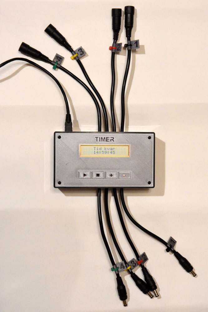
This article describes a simple timer that disconnects a number of lithium ion batteries from their chargers after a predetermined time. The timer consists of a Teensy LC (Arduino compatible) processor board, a 2×16 alphanumeric LCD, MOSFETs to connect/disconnect the chargers and batteries and a few 3D-printed parts.
Why it is needed
The youth section of my local orienteering club has a few head lamps to lend out during trainings to kids who do not have their own. The batteries need to be charged after each use, but it might be several days or even weeks before the leaders are back at the club house to disconnect the batteries from the chargers. There are reports of accidents where the chargers or batteries have caught fire in situations like this, so it would be good if the charging time could be limited.
The first idea was to put a timer on the mains supply to the chargers. After a quick investigation, I noticed that the chargers actually consume current from the batteries when they are not plugged into mains (an LED on the chargers is even lit in this case), so this was not a good solution as the batteries would be empty after a week or two in this state.
Instead I decided to build a timer that interrupts the DC connection between the chargers and batteries rather than the mains supply to the chargers.
Circuitry
As the processor board I decided to use a Teensy LC board, which is a pretty small and inexpensive “Arduino compatible” board (i.e. it can be programmed in the Arduino environment) with an ARM Cortex-M0+ processor. It has 27 I/O pins, which is more than enough for this simple application. The Arduino/Teensy environment provides useful and time-saving libraries for controlling the alphanumeric LCD, doing switch debouncing and keeping track of the time.
As the user interface, I decided to use a 2×16 LCD together with four push buttons. The LCD can be used in either 8-bit or 4-bit mode and I opted for the 4-bit mode since it requires fewer wires to be soldered between the Teensy and the LCD. The LCD also needs a potentiometer to control the contrast. Without that, or with the wrong setting of the pot, it will probably not show any characters at all.
I connected four momentary closing push buttons between pins on the Teensy and GND. By enabling internal pull-ups on these pins, no resistors are needed – reducing the amount of soldering required.
All of the pieces described so far are mounted to the back of a 3D-printed front panel as shown in the photo below.
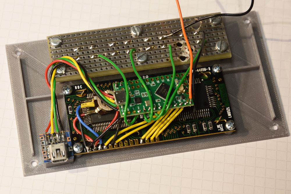
The USB signals are brought out to a separate mini-B connector mounted so that it is close to the side of the enclosure. The LCD is powered directly from the USB 5-V line. The 10-kohm potentiometer that provides the contrast signal to the LCD is connected between the LCD VCC pin (5 V) and GND. The push buttons are soldered to a scrap piece of perf board which is screwed to the front panel. Since the Teensy LC board is so small and lightweight, it works fine to just have it hanging in its short wires behind the LCD. An alternative would be to solder a few unused pins of the Teensy to the perf board.
The connection between the pieces are so few that they can rather easily be determined from the photo above. The code shown at the end of this post also defines which pins are used for what on the Teensy.
One pin of the Teensy controls the MOSFETs via the orange wire in the photo above. The MOSFETs are located on a separate piece of perf board, where most of the soldering in this project takes place:
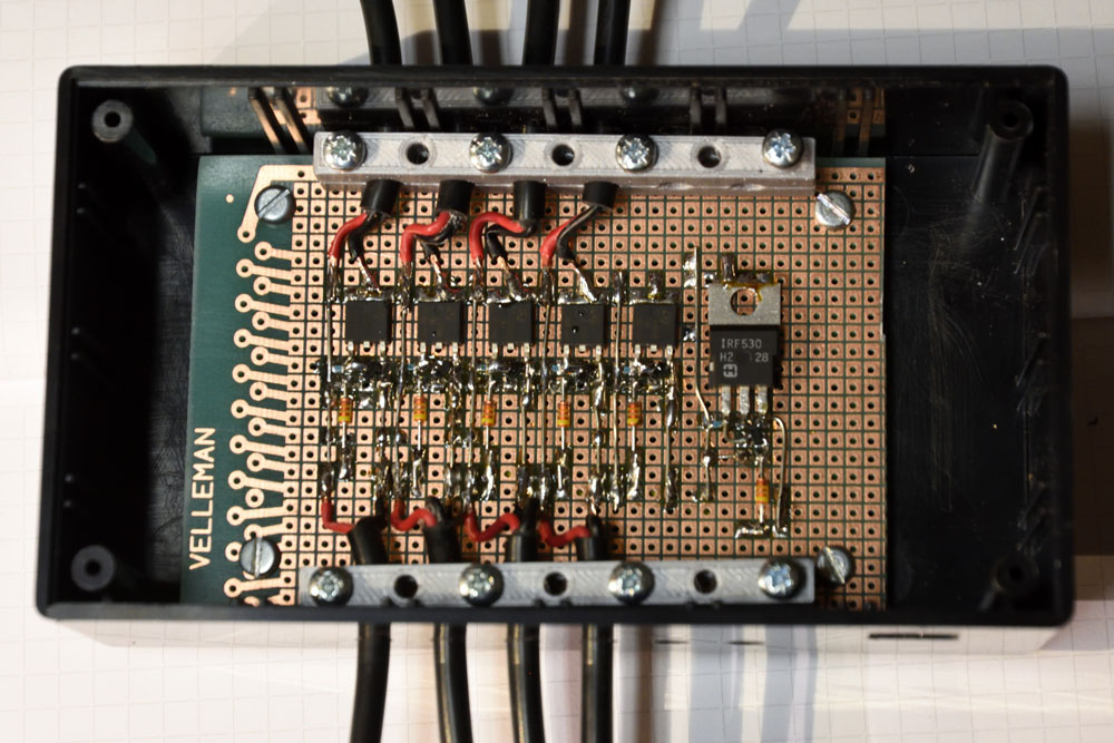
I used MOSFETs I had on hand, but unfortunately, I did not have six identical ones, so one of six channels is equipped with a different kind of transistor. The schematic for each of the channels is shown below:
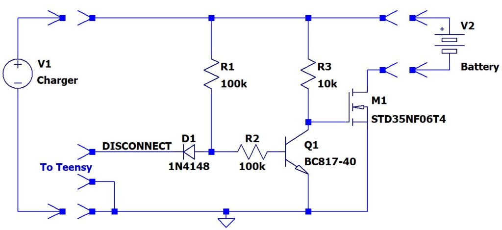
I did not want to control the MOSFET (M1) with the 3.3 V signal coming directly from the Teensy, since it might not turn on well enough with just 3.3 V. Instead I used a pull-up (R3) to the roughly 8-V voltage coming from the charger. When the NPN transistor Q1 is on, it pulls the gate of M1 low and thus turns it off and disconnects the battery from the charger. When the Teensy pulls the DISCONNECT signal low, the base current of Q1 (coming via R1) is diverted so that Q1 turns off and R3 can pull the gate of M1 high. Thus M1 turns on and connects the battery to the charger.
There is just a single DISCONNECT signal from the Teensy, connected to all the channels. The channels also share the same GND.
The Teensy is powered via a separate USB cable, so there could be a situation where the Teensy is unpowered, while there are chargers and batteries attached to the timer. I wanted the batteries to be disconnected from the chargers in this case and that is the reason for the diode D1. When the Teensy is unpowered, any of its pins will probably be about a diode drop (ESD diode) above GND if a small current is flowing into the pin. This might be a low enough voltage to prevent Q1 from turning on and M1 would be on, which I do not want. By adding the diode D1 in series with the DISCONNECT signal, we can be pretty sure Q1 will have enough base current to be on even when the Teensy is unpowered, and thus the batteries will be safely disconnected from the chargers in this case.
The MOSFETs I used (mostly STD35NF06T4) as M1 are vastly overkill in that they can handle much larger currents and much higher voltages than what will actually be needed here, so cheaper and smaller devices would work just as well. But I used what I had on hand that would fit the bill and I found no smaller suitable devices in the junk bin.
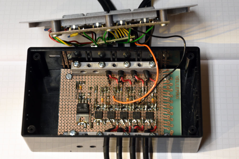
To connect the chargers and batteries to the timer, I used extension cords that were supplied with the headlamps, but which are not really needed when the lamps are used for running at night. I cut these cables in half and soldered them to the MOSFET board. Unfortunately only four such cables were available, so I will have to add two more in the future to enable channels five and six.
Mechanics
As the main part of the enclosure, I used a CU-1874-B box from Bud Industries, but as mentioned above, I replaced the lid with a custom 3D-printed part I designed in Fusion 360. It has screw posts for the display and for the board with the switches, as well as rectangular walled holes for 3D printed buttons that push on the switches. The front also has some reinforcements to make it more sturdy, although it gets pretty sturdy anyway when the LCD and the switch board have been screwed into it.

I designed the screw posts so that M2.5 (for the LCD) and M3 (for the switch board) screws could be self-threaded into them. The holes are square with sides of 2.1 mm for M2.5 and 2.6 mm for M3. The entrances of the holes are chamfered to make it easier to start the threads.
To mount the MOSFET board to the bottom of the box, I 3D-printed a frame (also with screw posts) that I then glued to the bottom of the box using CA glue. This way I did not have to drill any screw holes in either the front or the bottom of the box.

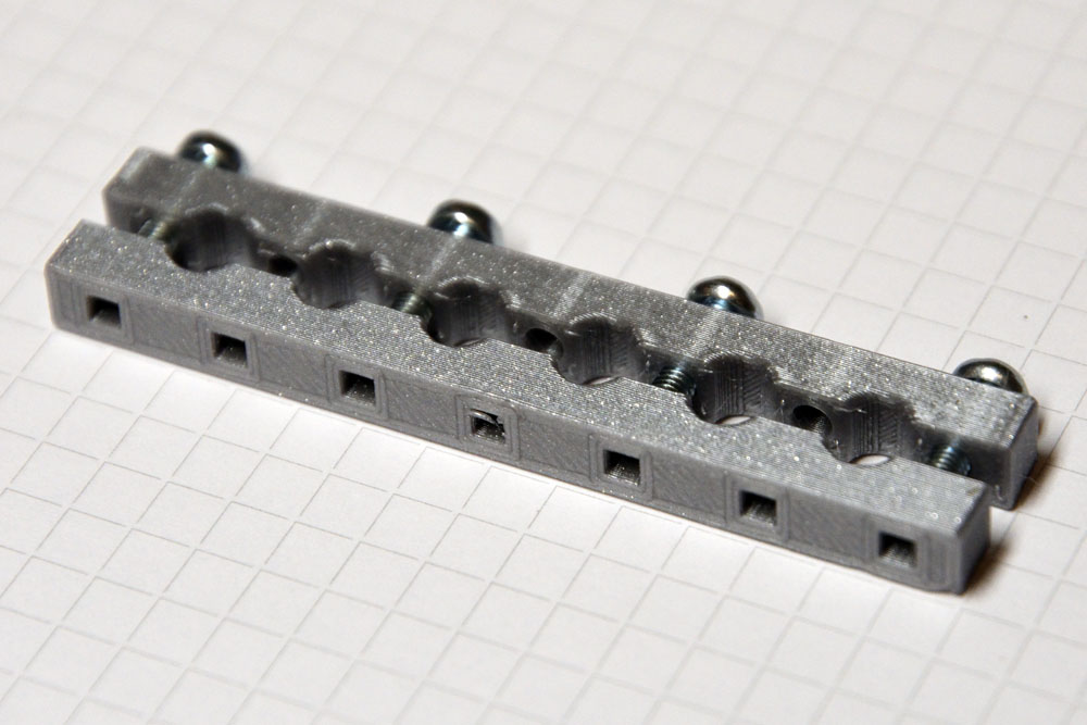
I wanted to have proper strain reliefs on the cables and I 3D-printed those to fit all six cables at once. Again with square holes to allow M3 screws to self-tap into the material.
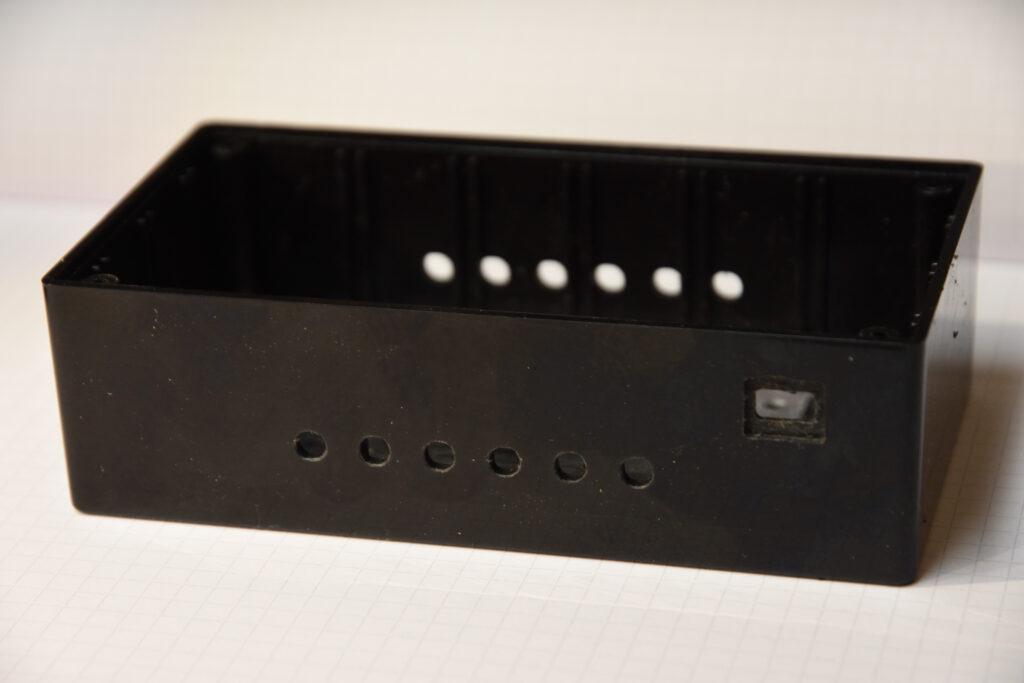
Even though no screw holes were needed in the box, there still had to be holes for the cables and for the USB connector to power (and if necessary reprogram) the Teensy. Since I have a CNC machine, I used that to mill these holes. The cable holes could easily have been made with simpler tools, but the wall around the USB hole had to be thinned for a proper fit of the connector and this was easier done with the CNC than with alternative methods.
Code
The program running in the Teensy is a simple Arduino “sketch”. The LiquidCrystal library is used for communication with the LCD and the Bounce2 library is used for button debouncing. Time is kept by an elapsedMillis timer, a variable that automatically increments every millisecond.
The setup() routine – which is automatically called once at the beginning of an Arduino sketch – defines a custom LCD character (a right-arrow, play-symbol) used on the start screen to refer to the button to press to start the charging. It then sets up the I/O lines used for the four buttons; start, stop, increment and decrement. The line for the DISCONNECT pin and the on-board LED are set up as outputs.
The loop() routine is automatically called over and over again, indefinitely, in an Arduino sketch. In this case, it contains a simple state machine that keeps track of whether the timer is running or if it is stopped. If it is stopped, it only reacts to the start (or “play” if you will) button. By default, it starts a 15 hour countdown when play is pressed.
If instead the timer is already running, it will react to either increment, decrement or stop. Stop is self explanatory, while increment and decrement increase or decrease the remaining time. Initially the steps are 1 hour, but when the remaining time is lower, the steps are reduced accordingly. A maximum time of 48 hours have been defined earlier in the program.
When the timer is running, the LCD shows the remaining time in the format HH:MM:SS and this is updated every second. The LED is also toggled every second, although this will not be visible to the user as it is embedded deep in the opaque box.
Finally the program contains a few functions to help with showing information on the LCD.
Here is the complete code:
/* Head lamp charge timer.

   Disconnects a charger from a (head lamp) (LiIon) battery after a given time
   to reduce the risks of having a charger connected for a long time to
   a LiIon battery.

   The user interface consists of a 2x16 LCD panel and some buttons.

   Target: Teensy LC

   Written by Per Magnusson, http://www.axotron.se
   v 1.0 2021-01-08
   This program is public domain.
*/

#include <Arduino.h>
#include <LiquidCrystal.h>
#include <Bounce2.h>

static const int32_t DEFAULT_TIME = 15*60*60*1000; // In milliseconds
static const int32_t MAX_TIME     = 48*60*60*1000; // In milliseconds
static const int32_t TIME_STEP    =  1*60*60*1000; // In milliseconds
static const int32_t TIME_STEP2   =    10*60*1000; // In milliseconds
static const int32_t TIME_STEP3   =     1*60*1000; // In milliseconds
static const int32_t TIME_STEP4   =       10*1000; // In milliseconds


// Stated
static const int32_t STATE_OFF = 0; // Not charging
static const int32_t STATE_ON  = 1; // Charging


// Pins
static const int START_PIN = 2;       // Start timer (and turn charging on)
static const int STOP_PIN = 3;        // Stop timer (and turn charging off)
static const int INC_PIN = 4;         // Increment timer by 1 hour
static const int DEC_PIN = 5;         // Decrement timer by 1 hour
static const int DISCONNECT_PIN = 12; // High disconnects charger from battery

// LCD           RS  E D4 D5  D6  D7
LiquidCrystal lcd(6, 7, 8, 9, 10, 11);

static const int LED_PIN = 13;

elapsedMillis timer;
uint32_t end_time;
int32_t state;

Bounce b_start = Bounce();
Bounce b_stop = Bounce();
Bounce b_inc = Bounce();
Bounce b_dec = Bounce();

// Custom character
byte play_glyph[] = {
  B00000,
  B10000,
  B11000,
  B11100,
  B11110,
  B11100,
  B11000,
  B10000
};
const byte play_char = 0;


void setup()
{
  Serial.begin(57600);
  lcd.begin(16, 2);
  lcd.createChar(play_char, play_glyph);

  b_start.attach(START_PIN, INPUT_PULLUP);
  b_stop.attach(STOP_PIN, INPUT_PULLUP);
  b_inc.attach(INC_PIN, INPUT_PULLUP);
  b_dec.attach(DEC_PIN, INPUT_PULLUP);
  b_start.interval(25);
  b_stop.interval(25);
  b_inc.interval(25);
  b_dec.interval(25);

  timer = 0;
  end_time = 0;
  state = STATE_OFF;

  pinMode(DISCONNECT_PIN, OUTPUT);
  digitalWrite(DISCONNECT_PIN, HIGH);

  pinMode(LED_PIN, OUTPUT);
  digitalWrite(LED_PIN, HIGH);
  lcd_splash();
  digitalWrite(LED_PIN, LOW);
  Serial.println("Charge timer");
}


void loop()
{
  static uint32_t last_update = 0; // The last time the display was updated

  b_start.update();
  b_stop.update();
  b_inc.update();
  b_dec.update();

  if(state == STATE_OFF) {
    // Timer is off
    if(b_start.fell()) {
      // Start timer
      timer = 0;
      end_time = DEFAULT_TIME;
      state = STATE_ON;
      digitalWrite(DISCONNECT_PIN, LOW);
      digitalWrite(LED_PIN, LOW);
      lcd_update();
      last_update = 0;
    }
  } else {
    // Timer is on
    if(timer > end_time) {
      // Time has run out
      state = STATE_OFF;
      digitalWrite(DISCONNECT_PIN, HIGH);
      lcd_done();
    } else if(b_stop.fell()) {
      // The stop button was pressed
      state = STATE_OFF;
      digitalWrite(DISCONNECT_PIN, HIGH);
      lcd_stop();
    } else if(b_inc.fell()) {
      // Increment time
      if(end_time - timer < TIME_STEP3) {
        end_time += TIME_STEP4;
      } else if(end_time - timer < TIME_STEP2) {
        end_time += TIME_STEP3;
      } else if(end_time - timer < TIME_STEP) {
        end_time += TIME_STEP2;
      } else {
        end_time += TIME_STEP;
      }
      if(end_time > MAX_TIME) {
	      end_time = MAX_TIME;
        timer = 0;
        last_update = 0;
      }
      lcd_update();
    } else if(b_dec.fell()) {
      // Decrement time
      if(end_time - timer < TIME_STEP3 + 3 * TIME_STEP4) {
        end_time -= TIME_STEP4;
      } else if(end_time - timer < TIME_STEP2 + 5 * TIME_STEP3) {
        end_time -= TIME_STEP3;
      } else if(end_time - timer < TIME_STEP + 3 * TIME_STEP2) {
        end_time -= TIME_STEP2;
      } else {
        end_time -= TIME_STEP;
      }
      lcd_update();
    }
    if((state == STATE_ON) && (timer > last_update + 1000)) {
      lcd_update();
      last_update = (timer / 1000) * 1000;
      if(digitalRead(LED_PIN)) {
        digitalWrite(LED_PIN, LOW);
      } else {
        digitalWrite(LED_PIN, HIGH);
      }
    }
  }
}


// Draw the splash screen
void lcd_splash()
{
  lcd.clear();
  lcd.noCursor();
  lcd.noBlink();
  lcd.setCursor(0, 0);
  //         0123456789012345
  lcd.print(" Laddningstimer "); // Charging timer
  lcd.setCursor(0, 3);
  //         0123456789012345
  lcd.print("    Tryck "); // Press
  lcd.write(play_char);    // >
}


// Draw the screen showing that charging has finished
void lcd_done()
{
  lcd.clear();
  lcd.noCursor();
  lcd.noBlink();
  lcd.setCursor(0, 0);
  //         0123456789012345
  lcd.print("    Laddning    "); // Charging
  lcd.setCursor(0, 3);
  //         0123456789012345
  lcd.print("      klar      "); // done
}

// Draw the screen showing that charging has finished
void lcd_stop()
{
  lcd.clear();
  lcd.noCursor();
  lcd.noBlink();
  lcd.setCursor(0, 0);
  //         0123456789012345
  lcd.print("    Laddning    "); // Charging
  lcd.setCursor(0, 3);
  //         0123456789012345
  lcd.print("    avbruten    "); // interrupted
}

// Convert a positive number between 0 and 99 to a nul-terminated
// string with two digits. The first character is 0 for numbers below 10.
void int_to_00str(uint32_t num, char *str) {
  str[2] = '\0';
  str[1] = (num % 10) + '0';
  str[0] = (num - (num % 10))/10 + '0';
}


// Convert a positive number between 0 and 999 to a nul-terminated
// string with three digits. Leading zeros are replaced by spaces.
void int_to_3str(uint32_t num, char *str) {
  str[3] = '\0';
  str[2] = (num % 10) + '0';
  num -= (num%10);
  num /= 10;

  str[1] = ' ';
  if(num > 0) {
    str[1] = (num % 10) + '0';
    num -= (num%10);
    num /= 10;
  }

  str[0] = ' ';
  if(num > 0) {
    str[0] = (num % 10) + '0';
  }
}

// Update the countdown timer on the LCD
void lcd_update()
{
  uint32_t time_left;
  uint32_t seconds;
  uint32_t minutes;
  uint32_t hours;
  char sec_str[3];
  char min_str[3];
  char hour_str[4];

  time_left = end_time - timer; // ms
  if(time_left < 0) {
    time_left = 0;
  }
  time_left /= 1000; // s
  seconds = time_left % 60;
  time_left -= seconds;
  time_left /= 60; // minutes
  minutes = time_left % 60;
  time_left -= minutes;
  time_left /= 60; // hours
  hours = time_left;

  int_to_00str(seconds, sec_str);
  int_to_00str(minutes, min_str);
  int_to_3str(hours, hour_str);

  lcd.setCursor(0, 0);
  //         0123456789012345
  lcd.print("    Tid kvar    ");
  lcd.setCursor(0, 1);
  //         01234567890123456789
  lcd.print("   ");
  lcd.print(hour_str);
  lcd.print(":");
  lcd.print(min_str);
  lcd.print(":");
  lcd.print(sec_str);
  lcd.print("    ");
}
