This article presents some slight improvements over the previous designs. The handle is less complicated and lighter and there is better protection for the elements from getting kinked. A drill guide for helping with drilling the holes in the elements is also included.
Like before, the tape measure elements can be rolled up on spools for storage and transportation:
The antenna/receiver can easily (with the help of a screwdriver) be further compacted for transportation:
Here is a link to a zip-file with the 3D models for printing:
Link to a zip-file with 3MF models of the parts:
New Features
The director (front) element is now protected from sharp bends by a clamping piece (blue in the figure below) that sticks out a little to the sides:
The reflector (rear) element has a clamp that extends further than before (blue in the figure below) to avoid sharp bends:
The driven elements are better protected from sharp bends by a piece that sticks out further than before (green in the figure below):
The handle is simpler. Now there are just two M3 screws that holds the clamp. No complicated pivoting clamp controlled by a long M4 screw through the handle. I have found this to work at least as well as the earlier version while being slightly lighter and easier to assemble.
It can be hard to drill the holes in the tape measure correctly. Both to get the holes in the correct positions and to get clean holes. To help with this, I designed a 3D-printed drill guide that is augmented with 5 mm thick steel plates:
There are five holes in the guide. The outer pair is for the front and rear elements. The inner pair is for the driven elements, while the center hole can be used when/if drilling holes at the tips of the elements for better traction when rolling them up on the spools.
The masking tape in the photo serves to adjust the amount of play between the pieces.
The steel plates have the dimensions 5x15x37 mm. Glue them in place in the recesses in the two pieces using epoxy. Use a drill press to drill 3.5 mm holes through the steel plates, using the holes in the 3D print as guides. The holes in the steel will then be what really guides the drill.
To use the drill guide, place the tape measure at the desired position in the bottom piece, put the top piece on and clamp it all securely together, e.g. using strong spring clamps, before using a drill press to drill the 3.5 mm holes.
Details
Here is a drawing with dimensions:
The shortest element is the director (towards the main lobe of the antenna) while the longest is the reflector. The “driven” element, connected to the receiver, is the one in the middle.
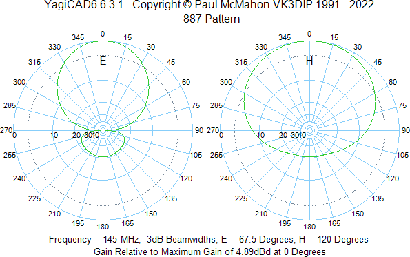
According to YagiCAD, the radiation pattern of the antenna is as follows:
For the boom, I use a piece of 16 mm outside diameter PVC electrical conduit pipe (“VP-rör” in Swedish). The boom is cut in the middle of the piece that holds the driven element so that the antenna can be further disassembled during transportation. The rear section is 347 mm long while the front one is 279 mm.
For the elements, I use 25 mm wide steel tape measure from Biltema, e.g. part number 16-2931. I taper the ends, round off the sharp edges with sand paper and put some sports tape over the edges both to protect from any remaining sharpness and to provide something for the screws in the spools to grab onto when rolling up the elements on the spools:
Throughout the design, M3 screws and nuts are used to hold the pieces together. Stainless screws and nuts should be used to prevent corrosion over time.
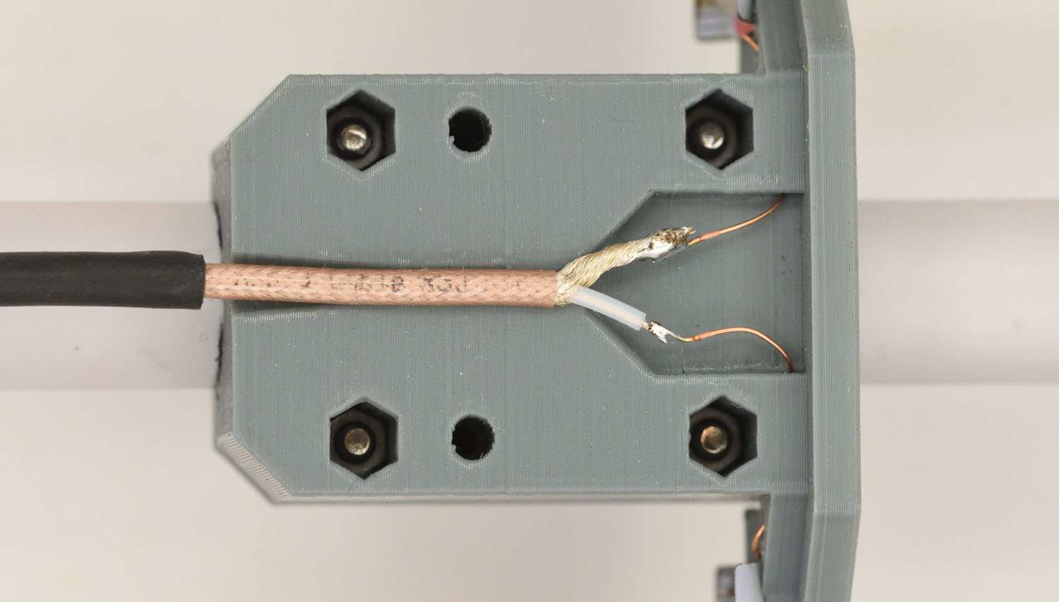
On the most recent antennas I have built, I have used a balun, CX2041ANLT, to interface the driven elements to the coax. The balun is soldered to a little PCB and placed in the recess in the part that holds the driven elements. A piece of standard perfboard could just as well be used instead of the custom PCB.
I have not checked if there is an actual difference in performance between antennas with this balun and without, like this:
The nuts for the screws that hold the combined cover and strain relief are square ones that fit into slots in the side of the part. It can be helpful to use tack-it or some other sticky substance to hold them in place before putting in the screws.
The grip of the handle around the boom is a little slippery. To avoid having the handle easily slip and rotate around the pipe while running, I made a little registration peg that can be glued onto the top of the pipe (preferably using epoxy). The gap in the handle clamp fits around the peg and prevents the handle from rotating. There are two holes in the peg where one can insert pieces of 3D filament to reinforce the glue joint. Corresponding holes obviously need to be drilled into the pipe as well. Be careful to place the peg in a suitable spot relative to the box with the electronics. There should be enough space behind it so that the handle is able to be pulled back and rotated during transportation or storage.
Handle pulled back and slightly rotated:
Handle in “use” position, locked from rotating by the peg.
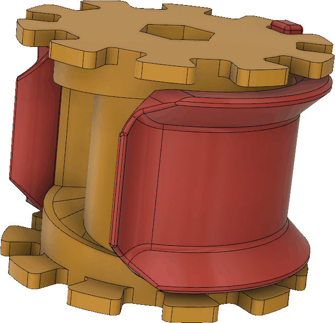
The spools and clamps that allow the tape measure elements to be rolled up for storage are perhaps the most intricate parts in this design. The spool and clamp together look like this:
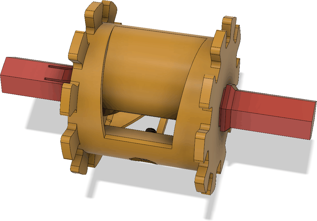
Six sets of spools/clamps are needed. To help when rolling up the tape measure onto the spool, there is also a hexagonal pin that fits in the center hole of the spool:
Only one such pin is needed per antenna as it can be moved between the spools. The M2.5 x 5 mm screw that is used as a hook for the tip of the tape measure when rolling it up is barely visible above.
I now recommend to print the spools and spool clamps as separate pieces, instead of utilizing the spool clamp as part of the support for the spool (as was suggested in the previous article). This increases print time, but reduces the manual work separating the pieces and the support material. The spool clamp prints without support, but the spool requires it:
All other pieces print without support.
Two spools in use (with the pin in place in one of them) is shown below:
I printed the spools using neon-orange filament to make them more easy to spot in most environments and thus reduce the risk of losing them.
I del 1 av den här tvådelade artikeln [1] beskrevs hur man från en Raspberry Pi Pico 2 (ett billigt litet mikrokontrollerkort) direkt kan skapa häpnadsväckande bra HF-signaler som bara behöver lite filtrering och antennanpassning för att gott och väl duga till en foxoringsändare för 80m-bandet (3,5 – 3,6 MHz). I denna andra del går vi vidare och bygger en hel sändare baserat på tekniken i del 1.
Filter och antennanpassning
Det behövs en transformator (eller annan balun) för att omvandla den differentiella signalen från processorns pinnar till en ensidig signal som kan matas till sprötantennen. Valet föll på en CX2041ANL från Pulse. Det är en liten ytmonterad 1:1 transformator gjord för 75 ohms impedans och med en förlust på max 0,8 dB i 80m-bandet. Efter omvandlingen sker lämpligen även lågpassfiltrering och någon sorts antennanpassning.
Jag mätte upp utimpedansen från processorn (efter transformatorn) med en nätverksanalysator och fann att den var drygt 100 ohm när båda utgångarna var höga, 90 när en var hög och en låg och 75 när båda var låga. Det vanligaste är att utgångarna har olika nivå, så 90 ohm får anses vara den typiska impedansen. Därför konstruerade jag ett 90-ohms femte ordningens lågpassfilter av chebyshevtyp med ca 4 MHz brytfrekvens. Efter lite itererande med brytfrekvens och rippelnivå i passbandet för att få ett standardvärde på spolarna (3,3 µH) och fint beteende mellan 3,5 och 3,6 MHz även när man simulerar med förlusterna i de valda spolarna, så landade jag i filtret i Figur 1.
Figur 1. 90-ohms Chebyshev lågpassfilter med 2,22 dB rippel och 3,75 MHz 3-dB-frekvens.
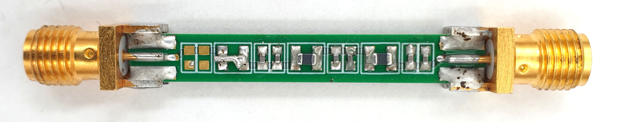
För att testa byggde jag filtret på ett litet filtermönsterkort jag hade liggande, se Figur 2.
Figur 2. Lågpassfiltret byggt som ett litet kretskort med SMA-kontakter.
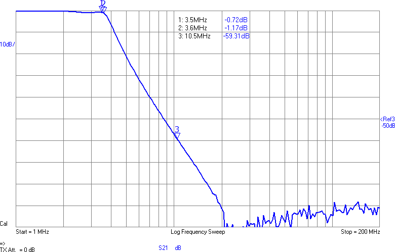
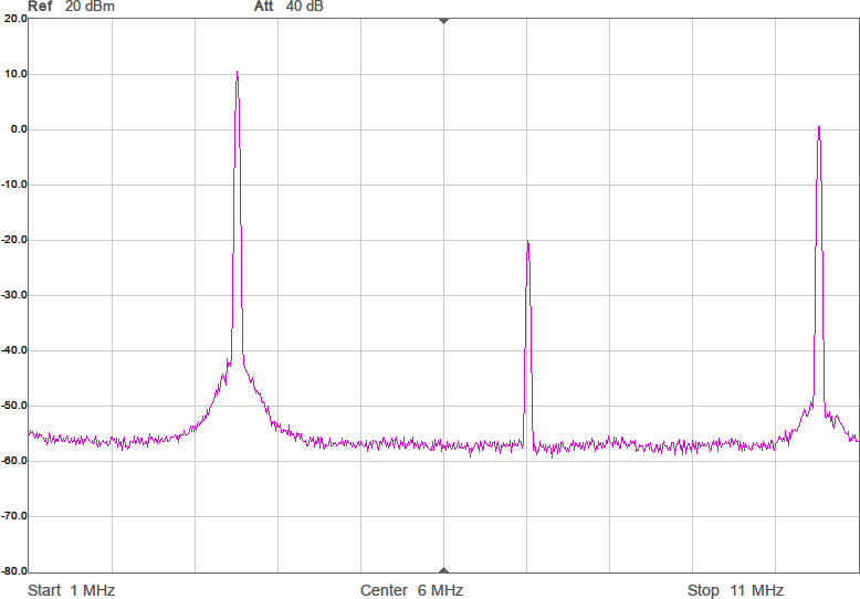
Uppmätt mellan 1 och 200 MHz på en nätverksanalysator (i 50-ohmsomgivning) har det responsen i Figur 3. Dämpningen vid tredje övertonen (10,5 MHz) är nästan 60 dB och förlusten i passbandet runt 1 dB. I verkligheten blir impedanserna som ansluts till filtret annorlunda (speciellt på antennsidan), men den här typen av filter är rätt robusta mot ändringar i omgivningen, så vi borde få vettig filterverkan ändå.
Figur 3. Lågpassfiltrets frekvensgång.
Med 90 ohms utimpedans och en matning till processorn på 3,3 V så kan man räkna ut maximal tillgänglig uteffekt genom att anta att man lastar med matchad impedans, dvs RL = 90 ohm. Toppvärdet över lasten är VP = 3,3/2 V= 1,65 V och max effekt i den är VP2/(2*RL) = 15 mW eller 12 dBm. Förluster i filter och transformatorer är gissningsvis ett par dB så i bästa fall 10 dBm (10 mW) borde i princip vara tillgängligt. Dock har den superkorta antennen (30 cm tänkte jag mig, vilket nog är en typisk antennlängd för en foxoringsändare) minst sagt usel verkningsgrad, så den mängd radioenergi som verkligen sänds ut är i praktiken väldigt mycket lägre. Med någon sorts impedansanpassning mot antennen borde det bli åtminstone signifikant bättre än om antennen kopplas direkt till utgången på filtret. En foxoringsändare ska dessutom inte leverera alltför mycket effekt eftersom det blir för enkelt då, så kanske behöver vi i slutändan dämpa signalen.
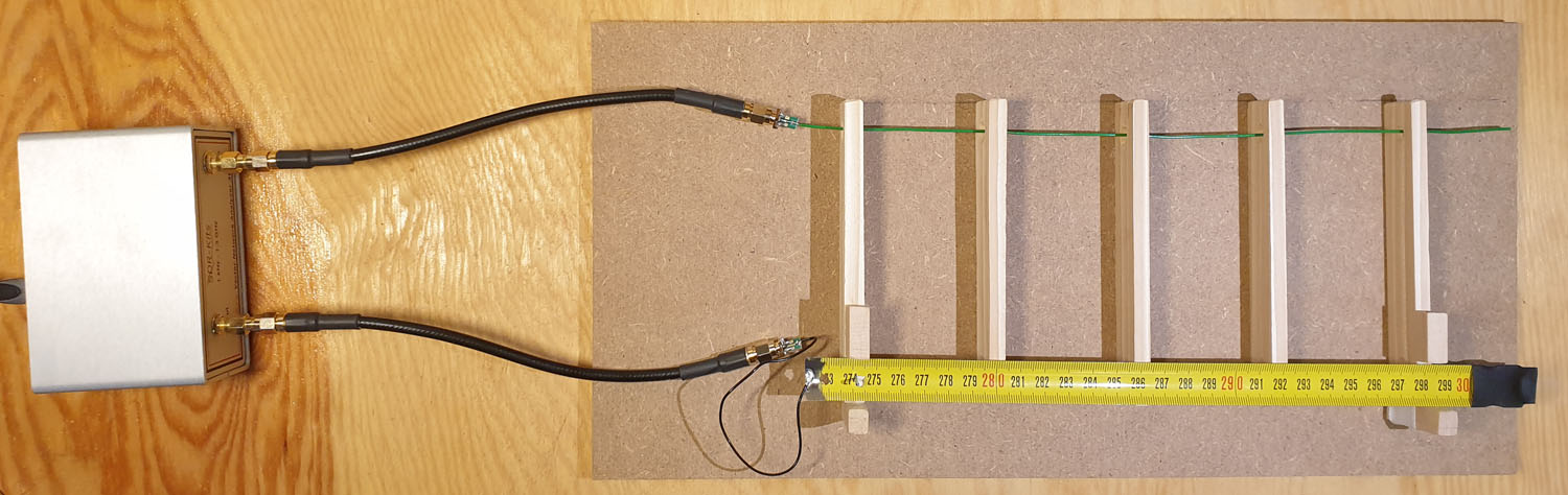
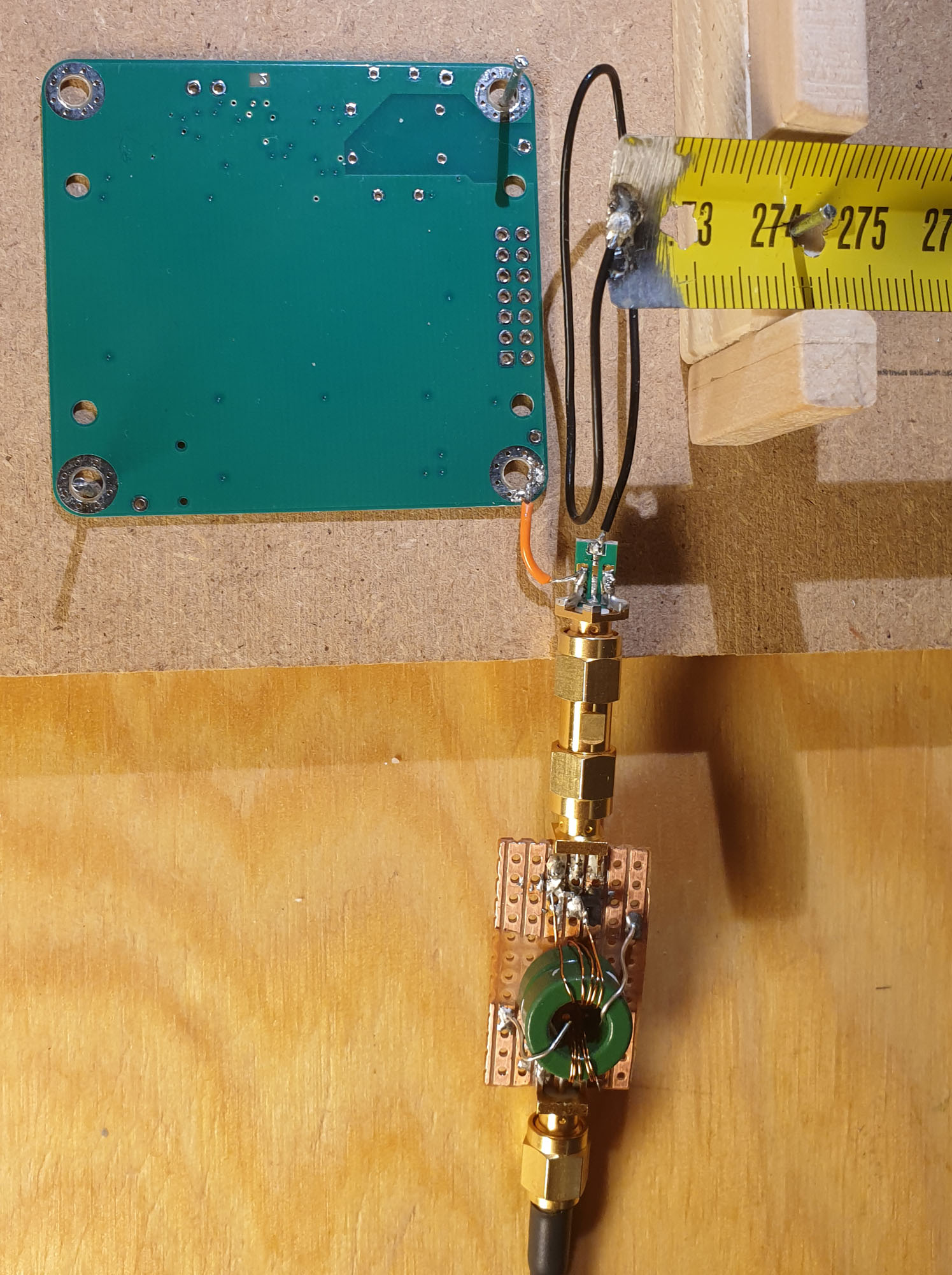
För att få ett relativt mått på effektiviteten hos olika anpassningar byggde jag en enkel testfixtur där sändarantennen hålls på 10 cm avstånd från en 30 cm lång mottagarantenn. Antennerna kopplas till de två portarna på en nätverksanalysator av typen VNWA och en överföringsfunktion, såväl som impedansen hos (den matchade) antennen kan därmed mätas upp. Se Figur 4.
Figur 4. Första ansatsen till fixtur för att mäta upp relativ prestanda hos olika antennanpassningar. Sändarantennen nedtill och mottagarantennen upptill. Båda ca 30 cm långa.
Det går att kritisera uppställningen på flera sätt: Mätningen sker i extremt närfält; mottagarantennens närvaro påverkar sändarantennens impedans en aning; omgivningen är inte kontrollerad eftersom det finns metall, elledningar och störande datorer i närheten; kablar och nätverksanalysator fungerar som motvikt/jordplan till antennen och har inte samma elektromagnetiska egenskaper som den batteridrivna foxoringsändaren som antennen ska kopplas till; det finns visst utrymme för att antennerna rör sig något mellan mätningarna, etc. Men trots alla brister bör bättre överföring mellan sändar- och mottagarantenn för en viss antennanpassning i denna fixtur ändå med stor sannolikhet innebära bättre funktion även i slutapplikationen. Speciellt om skillnaderna är markanta.
Efter en hel del arbete med att få till en bra antennanpassning med hjälp av mätningar i denna fixtur så insåg jag att den nog ändå inte var tillräckligt bra. Största felet är det där med att koaxkabeln på TX-porten tillsammans med VNA och USB-kabel fungerar som ett jordplan till antennen, vilket förbättrar dess effektivitet markant. Motsvarande kommer ju inte att finnas när det bara är ett litet batteridrivet kretskort som sitter i änden av antennen. För att avhjälpa detta lindade jag en transformator (un-un) på två Fair-Rite-toroider av material 43 och kopplade lindningarna till varsin SMA-kontakt. Lindningarna har 5 varv på vardera primär- och sekundärsidan och är placerade så långt från varandra som möjligt för att minimera kapacitansen. Minimal common-mode-koppling är alltså vad vi är ute efter så att inte kabeln till VNA:n kan fungera som jordplan till antennen. Lindningsinduktansen blev 19,5 µH och läckinduktansen 1,5 µH. 43 är ett material med rätt mycket förluster vid 3,5 MHz, men dämpningen är ändå bara 0,8 dB genom transformatorn i en 50-ohmsomgivning, så det får duga.
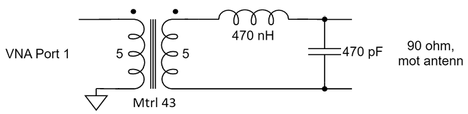
När ena sidan av transformatorn termineras med 50 ohm så är den komplexa impedansen 45 + i35 ohm på andra sidan vid 3,55 MHz. Eftersom utgången på filtret ska ha runt 90 ohms impedans i passbandet anpassade jag denna impedans till just 90 ohm. Det bör ge så rättvisande mätningar som möjligt mellan antennerna. Att transformera impedanser är ett standardproblem inom RF-elektronik. Ofta gör man det med LC-länkar och exempelvis på [2] finns en lättanvänd kalkylator som fungerar i det här fallet. Det som behövs är 448 nH i serie och 498 pF till jord. Jag valde standardvärdena 470 nH och 470 pF och resultatet blev utmärkt, inom ett par ohm från 90 ohm reell impedans. Schemat för det hela visas i Figur 5.
Figur 5. Transformator (un-un) i mätuppställningen för att inte få oönskat jordplan via VNA-kabeln, samt matchning mot 90 ohm på sekundärsidan.
Men sändaren har ju trots allt ett litet jordplan för antennen, nämligen kretskortets jordplan, så en realistisk modell av det behöver vara med i mätningarna. Eftersom jag redan tillverkat en första version av mönsterkortet så använder jag ett sådant, kopplat till ”jord” på antennsidan av transformatorn. Den modifierade delen av testuppställningen visas i Figur 6.
Figur 6. Närbild av den uppdaterade delen av mätuppställning med un-un nedtill och jordplan för antennen i form av ett mönsterkort med samma storlek som sändaren.
Som sändarantenn valde jag att använda en 30 cm lång bit av ett 19 mm brett stålmåttband (köpt på Jula). Stålmåttband tål att böjas, rätar ut sig av sig själv, är lätt att löda på om man slipar bort färgen och ett billigt 5m-band kostar bara några tior, så det är ett vettigt val för en sådan här antenn. I sändaren kommer det även att behövas en bit kopplingstråd, runt 10 cm lång, för att koppla antennen till kretskortet på ett bekvämt sätt, så en sådan tråd är också med i mätningarna.
VNA:n kan nu kalibreras. Jag valde att ha transformatorn inkopplad vid short-open-load-kalibreringarna så att man ser rättvisande impedanser när man kopplar in något bortom transformatorn, men jag körde utan transformatorn för thru- och thru-match-kalibreringarna.
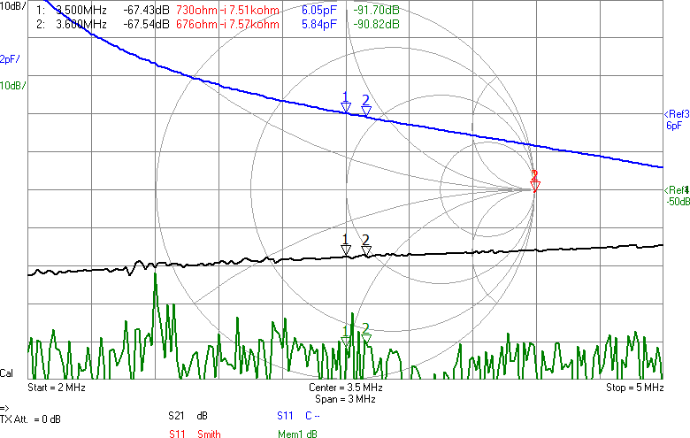
Första mätningen i fixturen blir att ta reda på antennimpedans och överföringsfunktion utan någon anpassning. Se Figur 7.
Figur 7. Antennmätning utan anpassning, mellan 2 och 5 MHz. Antennen är väldigt högimpediv och ser i princip ut som en kondensator på ca 6 pF. Signalen dämpas 67 dB. Den gröna kurvan visar brusgolvet. Markörerna visar gränserna för den del av 80m-bandet vi vill sända i.
Den svarta kurvan (S21) visar att signalen dämpas 67 dB mellan antennerna. I bakgrunden finns ett Smith-diagram och där ligger alla S11-värden i princip längst till höger, vilket innebär att antennen har (mycket) hög impedans. Smithdiagrammet är som vanligt ritat relativt 50 ohm, så punkten vi egentligen vill matcha mot, 90 ohm, ligger lite till höger om mitten av diagrammet. VNWA-mjukvaran kan omvandla reflektionskoefficienten S11 till komplex impedans (se texten för markörerna högst upp i bilden) och av den framgår att impedansen huvudsakligen är imaginär och negativ, dvs kapacitiv, vilket inte kommer som någon större överraskning. Med tanke på att impedansen är kapacitiv är det även intressant att plotta kapacitans som funktion av frekvens och av den blå kurvan framgår att vid 3,5 MHz ser antennen ut som en kapacitans på 6 pF. Men kapacitansvärdet är väldigt känsligt för placering av t.ex. ledningen mellan SMA-kontakten och antennen. Det är dessutom vanskligt att mäta så här höga impedanser med en VNA som är mest noggrann i närheten av 50 ohm, så det exakta värdet får man ta med en stor nypa salt.
Antennen är alltså väldigt högimpediv och impedansen därför blir känslig för små variationer i omgivningen till antennen. Men vi vill helst ha en robust konstruktion som inte påverkas så mycket av hur kabeln råkar hamna eller om det finns ett träd någon decimeter från antennen.
En sak man kan göra för att minska känsligheten är att placera en kondensator parallellt med antennen. Det bör stabilisera impedansen och göra att små ändringar i omgivningen får mindre inverkan. Jag valde 22 pF, vilket bör ge en total kapacitans på runt 28 pF och en reaktiv impedans på -i*1,6 kohm vid 3,5 MHz. Nu skulle vi kunna sätta en spole i serie med denna för att komma i närheten av en reell impedans och för att göra det i trakten av 3,5 MHz behövs 72 µH. Vi testar med standardvärdet 68 µH. Resultatet framgår av Figur 8.
Figur 8. 22 pF parallellt med antennen och 68 µH i serie.
Nu börjar det likna något. Vi har minskat förlusten mellan antennerna med över 23 dB. Det är en förbättring med en faktor 200. Fortfarande är det en bit kvar innan den resistiva delen är 90 ohm, men vi är i alla fall inte mer än en faktor två ifrån. För övrigt lär denna resistans i allt väsentligt utgöras av förluster i spolen, snarare än utstrålad RF-energi.
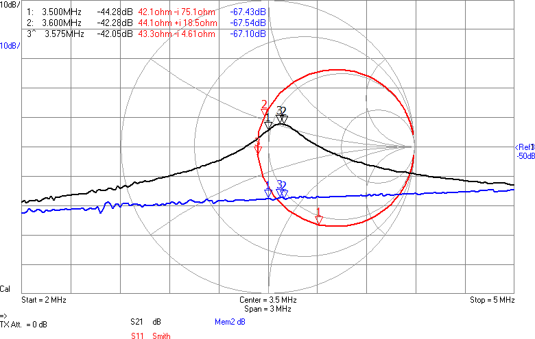
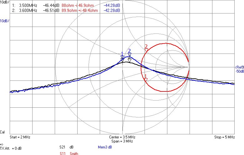
Något man skulle kunna önska är att kurvan vore flackare i bandet så att den frekvens man använder påverkar den utsända effekten mindre. Om vi chansar på att sändaren inte är på gränsen till att vara för svag så skulle man kunna lägga in lite dämpning i form av en resistans i serie med spolen för att minska Q-värdet. Eftersom vi ligger på runt 43 ohm i impedans nu och skulle vilja ligga på 90 ohm för att filtret ska fungera som det är tänkt, åtminstone i passbandet, skulle vi kunna testa med 47 ohm i serie med spolen. Figur 9 visar resultatet.
Figur 9. 47 ohm har lagts i serie med spolen (svart). Kurvan har blivit flackare (bra), impedansen mitt i bandet är 90 ohm reellt och signalen har dämpats 2-4 dB. Den blå kurvan visar hur det såg ut innan dämpningen lades till.
Vi har fått en dämpning på någon dB som väntat, men fördelen är att kurvan är flackare. Möjligen är det även en fördel att vi är nära 90 ohm i bandet. Efter att filtret kopplats in blir det som i Figur 10.
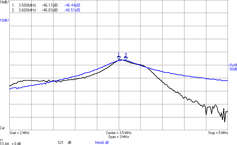
Figur 10. Filtret har kopplats in (svart) och ger minimal påverkan i bandet, samt dämpar högre frekvenser.
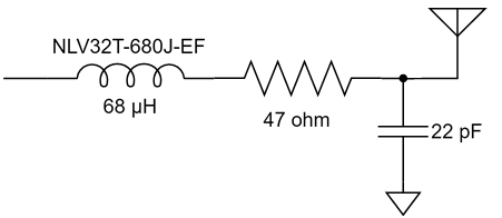
Amplituden har nästan inte påverkats i bandet, men vid högre frekvenser ser man hur filtret gör sitt jobb genom att undertrycka dem. Schemat för anpassningen med dämpning visas i Figur 11.
Figur 11. Antennanpassning/dämpning.
Frågan är dock om vi får ut tillräckligt starka signaler för en foxoringsändare, så det är dags att testa den detaljen.
På EM (region-1-mästerskapen) 2024 hade jag en mottagare (en vidareutveckling av [3]) som kan uppskatta avståndet till en sändare genom att man först kalibrerar mottagaren mot sändarens styrka. Baserat på ovetenskapliga tester jag gjort i en skog i närheten dämpas signalen ungefär med 10,5 dB vid en fördubbling av avståndet, så det värdet används i mottagarens beräkning. Det går att spara flera kalibreringar i mottagaren och en av dem jag har kvar är den jag gjorde mot foxoringsändarna på EM, även om de varierade en hel del i hur starka de var. Så genom att rigga upp den nya sändaren och jämföra signalstyrkan på ett visst avstånd med förväntad signalstyrka går det att räkna ut hur mycket starkare eller svagare den nya sändaren är relativt sändarna på EM.
Sagt och gjort. Det visade sig att sändaren är runt 6-8 dB för stark! Anpassningen har kanske lyckats lite väl bra? Men att dämpa är lättare än att förstärka, så det är bara att välja var och hur det ska dämpas. Vi skulle kunna passa på att dela upp dämpningen på ett par olika ställen. Dels skulle man kunna spara lite ström genom att inte lasta processorpinnarna så hårt och dels skulle man kunna dämpa ytterligare nära antennen för att få den än mer bredbandig. Vi ha redan lite dämpning vid antennen, så jag valde att bara dämpa ytterligare vid processorn.
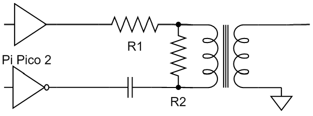
Dämpningen på utgången av processorn bör utnyttjas för att få så hög impedans som möjligt mot processorn så att vi sparar ström, medan 90 ohms impedans behålls mot filtret så att vi slipper designa om det. Här kan man sedan ändra resistansvärden för att justera amplituden utan att samtidigt behöva ändra någon anpassningskomponent. Schemat för dämpningen framgår av Figur 12.
Figur 12. Dämpning på processorutgången.
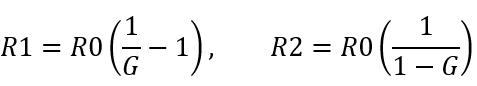
Med hjälp av lite algebra trillar formler ut för R1 och R2 som funktion av önskad ”förstärkning” enligt Figur 13:
Figur 13. Formler för dämparmotstånden.
Där G är önskad spänningsförstärkning (mindre än 1) och R0 är utimpedansen på processorn, tillika önskad impedans mot filtret, dvs 90 ohm. Om vi vill dämpa 6,5 dB blir G = 0,47. Det ger R1 = 100 ohm och R2 = 171 ohm. Vi kan välja standardvärdena 100 respektive 180 ohm.
Med denna ytterligare dämpning upplever jag sändaren som ungefär lika stark som de som användes på EM.
Kretskort
Nu är RF-kedjan klar och egentligen skulle det inte behövas så mycket mer elektronik för att få till en komplett foxoringsändare. Men jag ville lyxa till det lite på ett par olika sätt. Dels ville jag ha några omkopplare som man kan använda för att konfigurera sändaren utan att behöva koppla den till en dator och dels ville jag ha en liten display som talar om hur den är konfigurerad och vad batterispänningen är för att lätt kunna säkerställa att allt är i sin ordning inför användning. Tanken är att i normalfallet driva sändaren med tre AA-batterier, men om man får för sig att istället mata den från en power bank är det även praktiskt att ha möjlighet att periodiskt (kanske var 15:e sekund) dra en högre strömpuls för att övertyga strömsparfunktionen i powerbanken om att det visst finns en last inkopplad som fortfarande vill ha matning.
Anledningen till att ha AA-batterier som huvudalternativ framför t.ex. laddningsbara LiPo är för att det är mer kostnadseffektivt och praktiskt. Tre AA-batterier får man för under 10 kr medan ett lämpligt LiPo-batteri skulle kosta ungefär det tiodubbla. Med 2000 mAh kapacitet hos ett alkaliskt AA-batteri och en medelströmförbrukning på under 50 mA så räcker färska batterier i gott och väl ett dygn. För enkelhets skull är programkoden skriven så att sändaren alltid är aktiv när den har matning. Man slår alltså lämpligen på den när man sätter ut den i skogen och slår av den när man hämtar in den. Det här bör ge maximal sannolikhet att sändaren är påslagen när den ska vara det, speciellt om man är noga att kolla batteristatus i displayen innan man ger sig ut. En nackdel är att man inte bör sätta ut sändarna redan dagen innan loppet. Om man antar att det tar sex timmar från att man sätter ut en sändare till att man hämtar in den så räcker en uppsättning batterier med marginal till minst fyra lopp, även om man byter innan de är helt tomma. Det skulle alltså krävas ca 40 arrangemang innan man tjänat in de dyrare LiPo-batterierna. Med AA-batterier slipper man även krånglet med att ladda kanske 10 sändare efter ett lopp. Istället får man byta batterier ibland.
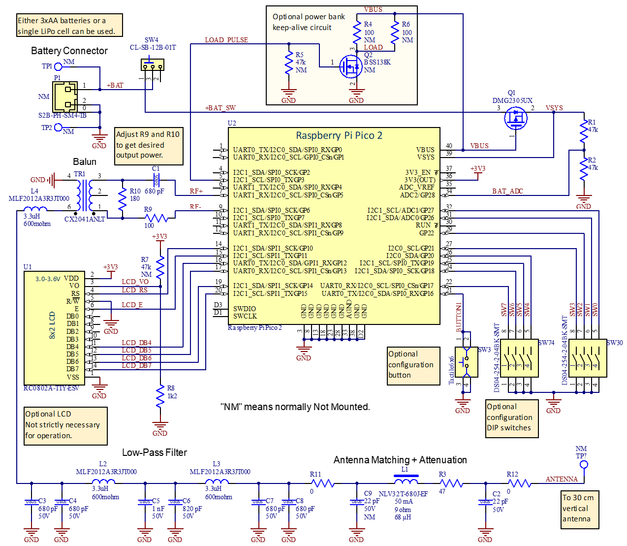
Det kompletta kopplingsschemat visas i Figur 14. Detta är en något förbättrad version mot vad jag själv byggde och innehåller den förenklade antennanpassningen som beskrivits ovan. På korten jag tillverkde finns istället en antennanpassning som även innehåller en transformator.
Jag lade förresten även till en spole (L4) före lågpassfiltret för att inte de högfrekventa komponenterna i sigma-deltasignalen ska se en låg impedans till jord. Detta minskar strömförbrukningen med någon mA. L4 är resonant med DC-blockningskondensatorn C1 före balunen vid ca 3,5 MHz, så den har minimal påverkan på filtret i 80m-bandet. Några ytterligare komponenter för att utöka möjligheterna till andra antennanpassningar finns också med, men monteras inte alls eller med nollohmsmotstånd.
Figur 14. Det kompletta kopplingsschemat för foxoringsändaren. Komponenter märkta NM ska normalt inte monteras och flera andra komponenter kan också uteslutas om man är ute efter en minimalistisk lösning.
Batterispänningen från en hållare med tre AA-batterier kommer in på TP1 och TP2 (alternativt kan man koppla in ett LiPo-batteri till P1, men det finns ingen inbyggd laddare). Med brytaren SW4 kan man slå av/på sändaren. Inbyggt i processorkortet finns en buck/boost-omvandlare som kan omvandla spänningar mellan 1,8 och 5,5 V till 3,3 V som driver processorn (och LCD:n). Under programmering matas det hela istället via USB-kabeln. Spänningen från USB-porten kommer ut på VBUS och slår av PMOS-transistorn Q1 som då kopplar bort eventuellt batteri. När USB-spänningen inte finns tillgänglig är Q1 påslagen och kopplar in batteripacken till VSYS som är ingången till buck/boost-regulatorn. R1-R2 är en spänningsdelare som gör att processorn kan mäta batterispänningen och visa den på LCD:n.
RF-signalerna kommer ut från processorkortet Pi Pico 2 på GP5 och GP6 och kopplas vidare till RF-kedjan med DC-blockering, dämpare, balun, filter och antennanpassning enligt tidigare beskrivning. Några extra komponenter har lagts till för att möjliggöra mer avancerade antennanpassningar, men monteras inte, eller med nollohmsmotstånd.
Processorn är även ansluten till en liten LCD för statusinformation och några omkopplare för konfigurering. Mer om det längre ned.
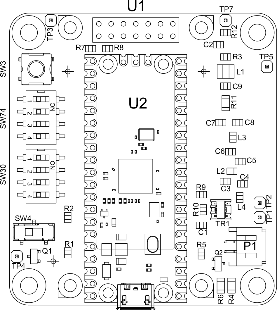
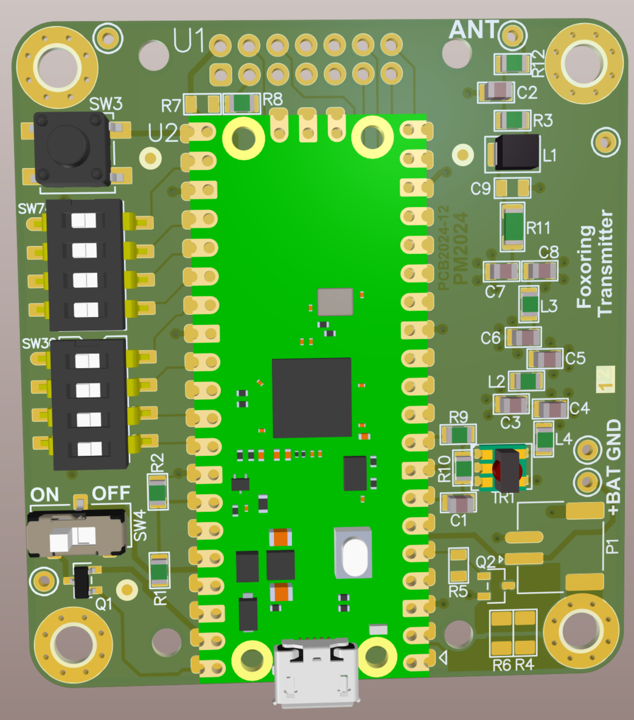
Monteringsritningen och en 3D-vy av kortet (utan LCD eftersom den skulle skymma många detaljer) visas i Figur 15.
Figur 15a. Monteringsritning av kortet utan LCD. En stor del av ytan upptas av Pi Pico 2-kortet, U2.
Figur 15b. 3D-vy av kortet utan LCD. En stor del av ytan upptas av Pi Pico 2-kortet, U2.
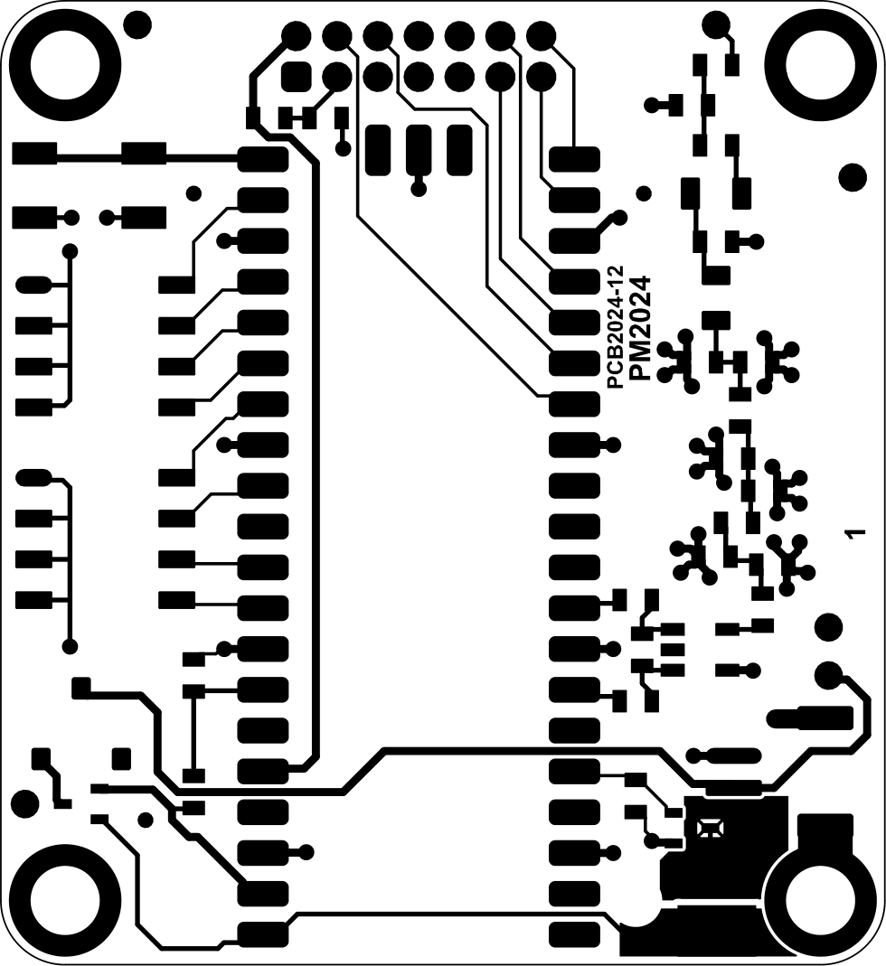
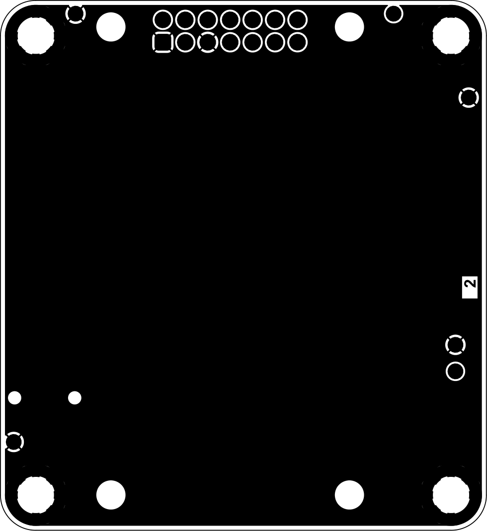
Kortet har två kopparlager, varav det undre enbart är ett jordplan. Alla ledningar gick att dra på ovansidan tack vare ett lämpligt val av vilka processorpinnar som används till vad. De två kopparlagren visas i Figur 16. Eftersom det inte är särskilt många komponenter på kortet och storlekskraven är modesta, så valde jag att använda större ytmonterade komponenter än jag normalt jobbar med. Alla kondensatorer, spolar och motstånd är av storlek 0805 eller större, vilket gör att de är ganska lätta att löda, även om någon form av förstoringshjälpmedel antagligen underlättar.
Figur 16a. Mönsterkortets topplager.
Figur 16b. Mönsterkortets bottenlager.
För att hålla nere den oönskade ströinduktansen hos kondensatorerna i filtret så att dämpningen vid höga frekvenser (100+ MHz) blir stor är kortet 0,8 mm tjockt istället för de vanligare 1,6 mm. Dessutom används fyra vior per kondensator för att ytterligare minska induktansen. Jag beställde 25 kort från JLCPCB och inklusive frakt och andra pålagor var den totala kostnaden drygt 700 kr. Kortets storlek är 55 x 60 mm, vilket bara är aningen större än en batterihållare för tre AA-batterier.
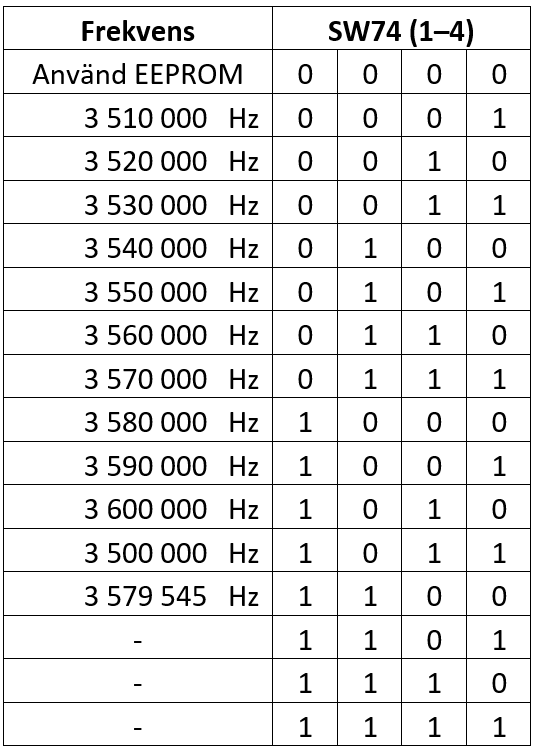
SW30 och SW74 är fyrdubbla DIP-brytare som kan användas för att välja funktion på sändaren. Så som programkoden är skriven för tillfället så väljer SW74 vilken frekvens som ska användas enligt Figur 17.
Figur 17. Funktionen hos DIP-brytare SW74.
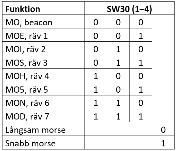
Om SW74 står på 0000 så används inställningarna i det icke-flyktiga minnet (SW30 ignoreras), vilket möjliggör annan frekvens, morsetakt eller morsetecken än man kan ställa in med omkopplarna. Oavsett inställning måste/bör man programmera in vilken anropssignal som ska användas genom att vid något tillfälle koppla upp sig via USB och lagra den i det icke-flyktiga minnet. Om SW74-inställningen är något annat än 0000 så är SW30 aktiv och anger rävnummer och om det ska sändas snabb eller långsam morse enligt Figur 18.
Figur 18. Funktionen hos DIP-brytarna SW30.
Brytarna läses dels av vid spänningstillslag och dels om man trycker på knappen SW3. Om man vill ha någon annan funktion på brytarna (t.ex. andra frekvenser) är det bara att ändra lite i programvaran. Om man nöjer sig med att ställa in funktionen genom att koppla upp sig med USB-kabel och ett terminalprogram så behövs inga brytare alls. Då gäller inställningen man gjort via kommandon i terminalfönstret och sparat till det icke-flyktiga minnet.
U1 är en liten tvåradig LCD med åtta alfanumeriska tecken per rad. Det var den minsta (och billigaste) alfanumeriska LCD som gick att mata med 3,3 V som jag hittade. Det kändes onödigt att göra sändaren väsentligt större på grund av storleken på en inte helt livsnödvändig LCD, så att hitta något litet var prioriterat. Tyvärr hade den ett fel i databladet som kostade många timmars felsökande. Det stod nämligen att ben 3 inte skulle anslutas, men i själva verket är detta (som på så många andra LCD:er) ett ben som ska kopplas till en spänningsdelare för att ställa in kontrasten på skärmen. När benet är oanslutet syns ingenting på displayen. Till slut visade det sig att det var lämpligt att koppla 1,2 kohm mellan jord och ben 3.
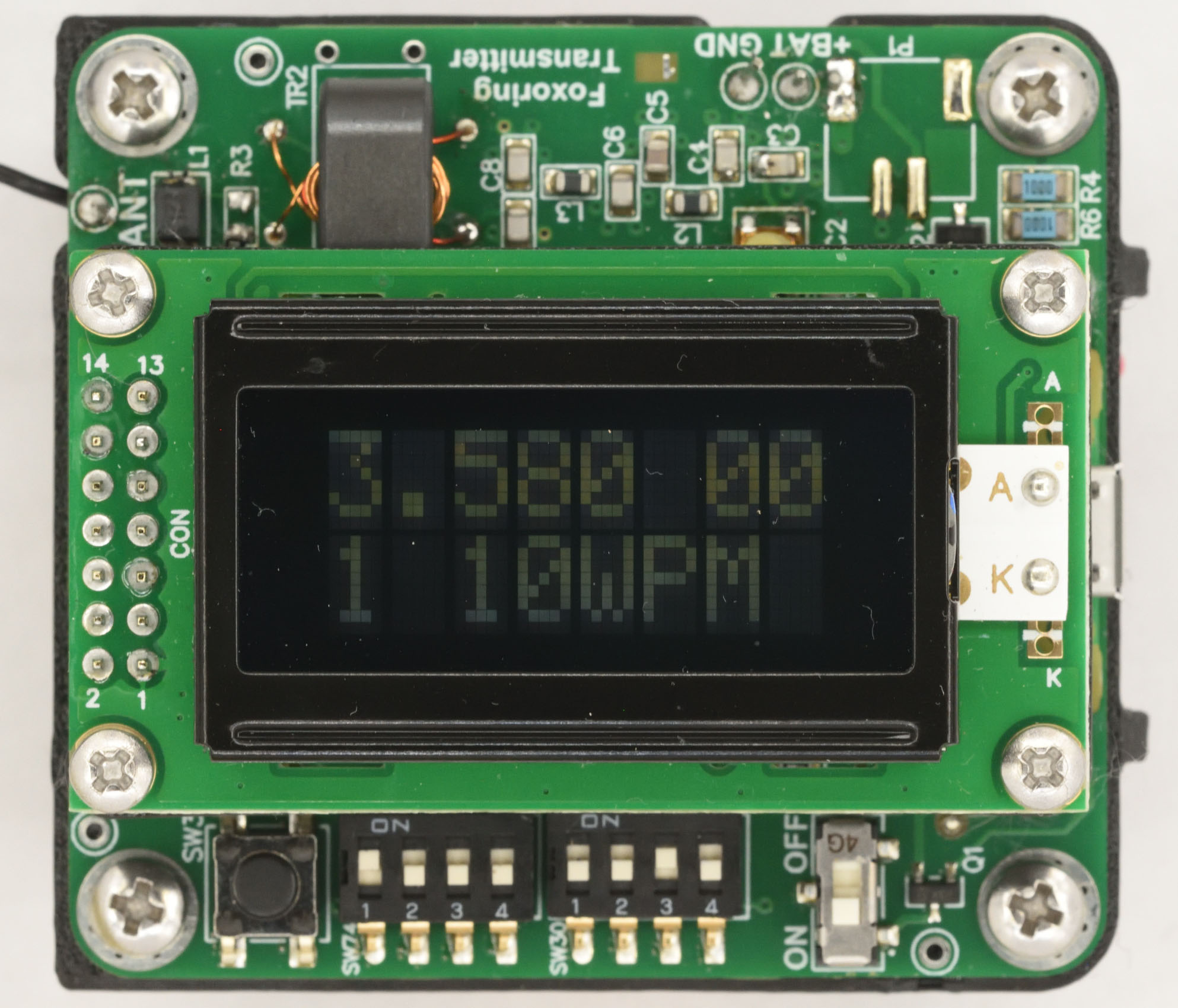
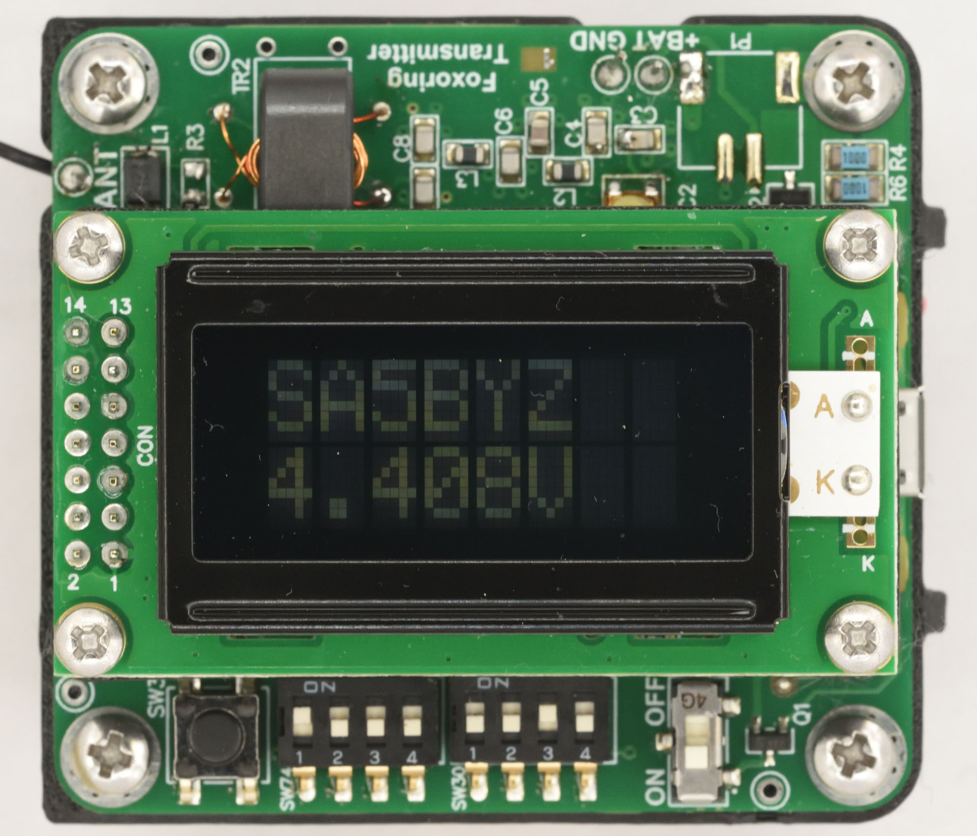
Eftersom LCD:n har så få tecken så växlar den hela tiden mellan att visa olika information. Se Figur 19.
Figur 19a. LCD:n växlar mellan två olika meddelanden. Här visas frekvens, rävnummer och morsetakt.
Figur 19. Här visas anropssignal och batterispänning.
Slutligen utgör Q2 och komponenterna runt den en möjlighet att periodiskt dra korta pulser med mer ström än normalt. Det är användbart om man matar sändaren via en power bank (kopplad till USB-porten) som envisas med att slå av sin utspänning om det inte dragits signifikant med ström på ett tag. Det kan behövas lite experimenterande och ändring i koden för att passa en viss power bank. Om sändaren drivs av batteri snarare än via USB-kabeln gör Q2 ingen skada eftersom en diod på processorkortet isolerar den från batteriet.
Mekanik
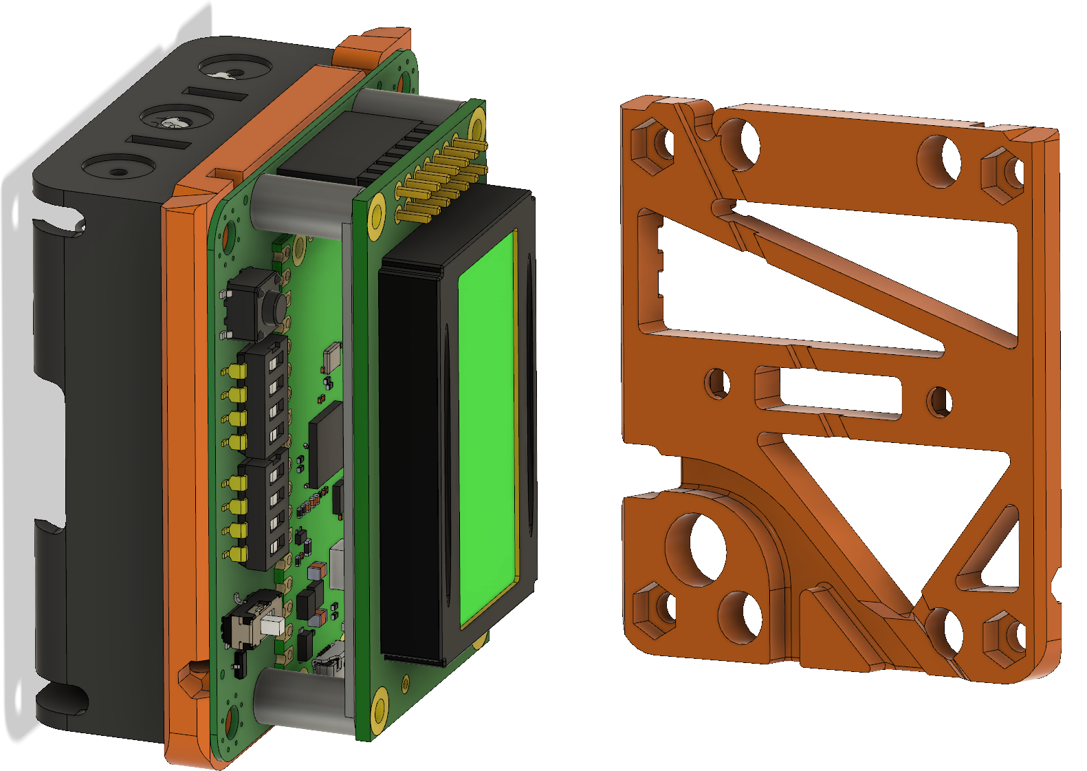
Sändaren behöver såklart byggas in i någon form av låda så att den tål att vara utomhus. En användbar finess vore om det gick att fästa lådan på ett ”glasfiberspjut” av den typ som ofta används på orienteringar för att hålla upp en elektronisk stämplingsenhet. Så brukar man göra på EM/VM och det är praktiskt om man ändå använder sådana spjut för att hålla stämplingsenheten. Eftersom jag har en 3D-skrivare så valde jag att rita ihop en lådkonstruktion som kan skrivas ut på den, vilket sparar in mycket jobb med håltagning och andra modifieringar som skulle behövas om man använde en standardlåda. Batterihållaren och kretskortet fästs på varsin sida av en mellanliggande 3D-utskriven fästplatta, se Figur 20. LCD:n hålls fast med M2,5-skruvar genom 3D-utskrivna distanser ovanför kretskortet. Detta utgör den kompakta kärnan i sändaren och den snäpper in i lådan utan några skruvar. När man vill byta batterier eller koppla in en USB-kabel kan man lätt snäppa ut elektronikpaketet genom att lätt böja ut övre delen av sidoväggarna.
Figur 20. Batterihållare, kretskort, LCD och mellanliggande fästplatta.
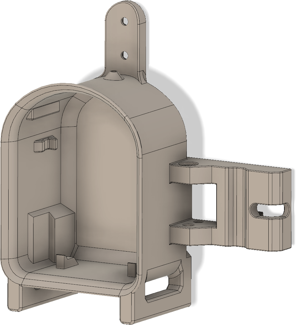
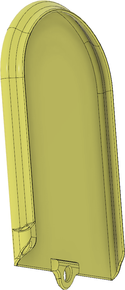
Lådan visas i Figur 21. Hela framsidan är öppen och har utsvängda kanter som dels fungerar som skenor för locket som skjuts på uppifrån och dels förhindrar regnvatten att rinna in. Inuti lådan finns styrklackar nedtill och snäppfästen på sidorna för elektroniken. Till höger finns en utskjutande del som ingår i anordningen för att hålla fast vid glasfiberspjutet. Upptill finns ett fäste för måttbandsantennen samt ett hål för ledningen till antennen. Hålet bör tätas med lim för att inte läcka in vatten. Nedtill finns fötter så att sändaren även kan stå upprätt på ett plant underlag. Fötterna har avlånga hål som man kan vika ned antennen i för att göra sändaren mindre skrymmande under transport.
Figur 21. Lådan.
Locket som visas i Figur 22 skjuts som sagt på ovanifrån och omsluter de utstickande kanterna runt öppningen. Det blir inte vattentätt, men åtminstone rimliga mängder regn som kommer uppifrån bör hållas ute. Nedtill finns en klack som gör att locket snäpper fast, samt ett hål där man kan knyta ett snöre mellan locket och lådan så att de inte kommer bort från varandra.
Figur 22. Locket.
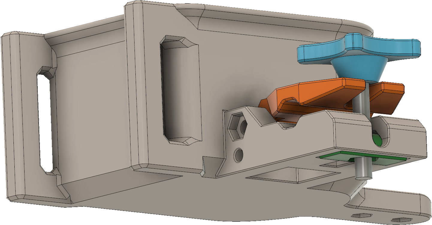
Mekanismen för att hålla fast lådan vid spjutet visas i Figur 23. Förutom delen som ingår i själva lådan finns en ledad klämma (orange) vars gångjärnspinne utgörs av en M4-skruv (syns inte i bilden), en M5-skruv med vingar (blå) och en rund, vridbar del med mutter (grön).
Figur 23. Mekanismen för att hålla fast lådan vid ett glasfiberspjut.
Lådorna jag skrivit ut hittills har blivit lite olika eftersom jag efter varje nytt exemplar kommit på någon förbättring att införa. Plasten jag använder är PETG som är seg, tål att vara utomhus, relativt billig och rätt lätt att skriva ut på de flesta 3D-skrivare. PLA som annars är vanlig i 3D-sammanhang kan nog inte rekommenderas eftersom den är ganska skör.
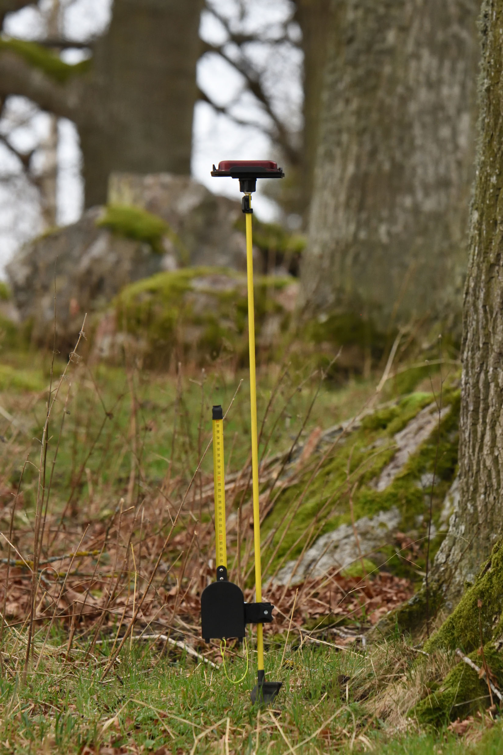
Hur det hela kan se ut när det är monterat på ett spjut framgår av Figur 24. För att det ska bli som på EM/VM ska antennen och spjutet målas svarta för att göra dem så svåra som möjligt att upptäcka för den som inte har full koll på pejlingen.
Figur 24. Sändaren ute i det fria, monterad på ett glasfiberspjut med elektronisk stämplingsenhet.
Bygg själv!
Om du vill bygga egna sändare av den här typen så finns programkod, underlag för mönsterkortet och 3D-modeller för lådan att ladda ned från [4]. Mönsterkorten går att beställa t.ex. från JLCPCB eller PCBWay. Om man vill ha en europeisk leverantör snarare än en kinesisk kan det vara värt att prova Aisler.
Möjliga förbättringar
Även om en del förbättringar redan är införda efter att jag tillverkade mina egna kort så finns det lite mer att göra om man vill. Här är några tankar:
Byt till ett Chebyshev-filter som börjar och slutar med en spole i serie istället för en kondensator till jord. L4 lades in i ett sent skede och man skulle få bättre nytta av den om den ingick i Chebyshevfiltret. Utgångsspolen kan då eventuellt också kombineras med antennanpassningsspolen, vilket sparar in en spole.
Det borde kunna bli tillräckligt bra (tillräcklig undertryckning av övertoner och tillräcklig effekt) utan att använda differentiell utgång (se del 1). Då slipper man den halvdyra balunen/transformatorn.
Möjlighet att slå av matningen till LCD:n via mjukvara för att spara ström i ett eventuellt sovläge.
Möjlighet att tända bakgrundsbelysningen till LCD:n vid väl valda tillfällen.
Programvara kan man alltid putsa på och det kräver inte nödvändigtvis några ändringar i hårdvaran. Tänkbara förbättringar är bland annat:
Förbättringar i sigma-delta-moduleringen med högre ordnings modulator och optimerade egenskaper hos dithering-bruset.
Optimering av strömförbrukningen. Kanske kan processorn sova mellan morsepipen?
Stöd för sovläge och realtisklocka så att man kan programmera den att börja och sluta sända vid givna tillfällen utan att den drar mycket ström när den inte sänder.
Bruksanvisning
Jag har skrivit en kort bruksanvisning för satsen med 12 sändare jag byggt:
En resa mot krångligare mjukvara för att med minimalistisk hårdvara få fina RF-egenskaper
Den här artikeln publicerades först i QTC nummer 1 2025.
Programkod, filer för kretskortstillverkning och 3D-modeller för den färdiga sändaren finns på https://github.com/per-magnusson/RP2350-Foxoring-Transmitter. Texten här i del 1 beskriver hur mjukvaran fungerar och utvecklades mot att generera allt bättre radiosignaler direkt från pinnar på processorn.
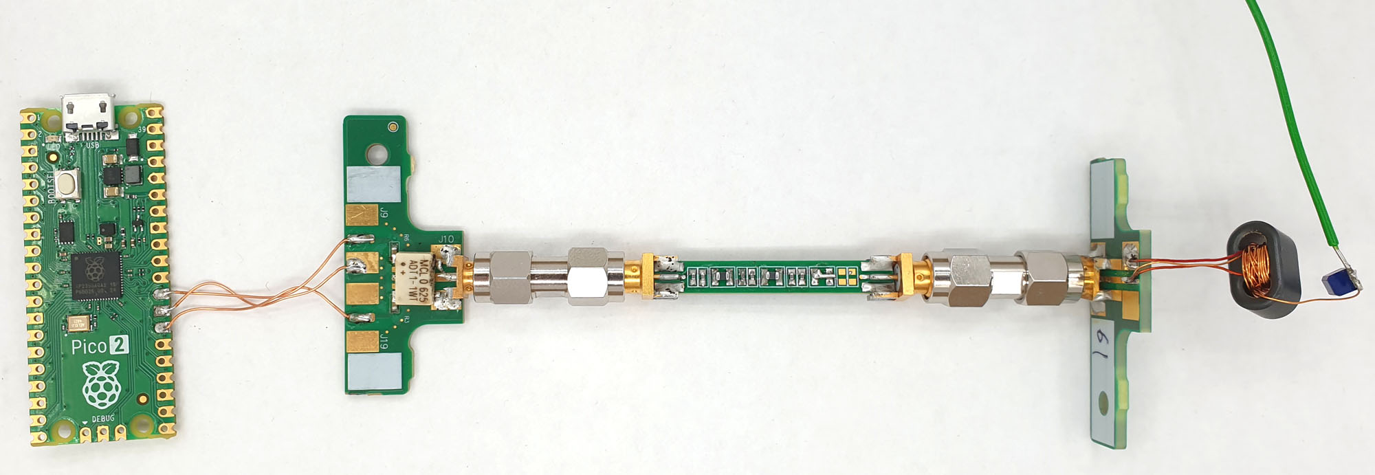
Figur 1. Sändarprototyp med Pi Pico 2, transformator, lågpassfilter och antennanpassning.
Foxoring är en variant av rävjakt/radiopejlorientering där man använder väldigt svaga sändare som bara hörs inom en radie av 100 m eller så. För att hitta fram till pejlbart avstånd från sändaren är den ungefärliga positionen inritad på kartan, så man orienterar sig fram till närheten av sändaren och pejlar sig fram sista biten. Foxoring är inte så vanligt i Sverige och förekommer varken på de nationella tävlingarna eller på något SM. Inte heller finns grenen med på NM, men väl på EM och VM, så kanske borde vi i Sverige köra foxoringträningar och -tävlingar lite oftare?
Personligen gillar jag grenen dels för att jag som i grunden är orienterare har en fördel av att jag behärskar orienteringsmomentet som är mer uttalat i denna tävlingsform än i vanlig rävjakt, dels för att de svaga signalerna sätter mottagaren på prov och gör att man har mer att vinna på att utveckla känsligare mottagare. För vanlig rävjakt på 80m-bandet är det inget större problem att bygga en tillräckligt lågbrusig mottagare och göra antennen tillräckligt känslig, men på just foxoring ger varje dB extra signal/brusförhållande en liten extra fördel eftersom man då kan höra sändaren på längre avstånd och tidigare styra in mot den.
För att testa mina egenbyggda mottagare satte jag för länge sedan ihop en enkel sändare där en Si5351 (ganska billig PLL/klockgenerator som är populär i amatörradiosammanhang) sköter både frekvenssyntes och agerar (svagt) slutsteg. Med en 3 m lång antenn hörs den på åtminstone 500 m avstånd. Så att använda en sådan, ihop med en processor som konfigurerar den och sköter morsesändandet, som grund för en foxoringsändare är en uppenbar möjlighet.
Via Peder Haugaard Pedersen, SM0GNS, fick jag dock tips om ett sätt att använda en Raspberry Pi Pico, alltså en litet kort med en mikrokontroller, att självständigt skapa signaler i 80m-bandet helt utan behov av en extern PLL eller oscillator. Färdiga kort med processorn RP2040 (och den nyare RP2350), USB-kontakt, minne och spänningsregulator kostar ca 70–80 kr, så det borde gå att konstruera en enkel, lättbyggd och billig foxoringsändare med ett sådant kort som bas. Och med väsentligt mycket lägre strömförbrukning än om man dessutom behöver en separat Si5351. Processorerna går att programmera i mikro-python samt C/C++ via t.ex. Arduinomiljön. Själv använder jag oftast det senare.
RP2040 och RP2350 har ett par unika och kraftfulla inbyggda periferienheter som kallas PIO (programmable input/output) och som är nyckeln till att dessa processorer går att använda som HF-generatorer. PIO-modulerna är en sorts enkla processorer som man kan programmera i ett begränsat assemblerspråk.
PIO med frekvensdelare
Peders lösning bygger på ett PIO-program med två instruktioner, lägg en utgång hög och lägg den sedan låg (och hoppa tillbaka till början). En praktisk funktion i PIO:n är att återhoppet till början av programmet kan ske utan att det tar någon extra tid, så programmet skapar alltså en symmetrisk fyrkantsvåg. Det lilla PIO-programmet ser ut så här:
.wrap_target
   set   pins, 1   ; Set output high
   set   pins, 0   ; Set output low
.wrap
På [1] finns en online-assemblator för PIO-program som omvandlar dem till C-kod som man kan inkludera i sitt C-program för att konfigurera PIO:n på önskat sätt.
En finess i varje PIO är att man kan skapa dess klocka genom att dela ned processorklockan. Neddelningsfaktorn kan vara ett bråktal med åtta bråktalsbitar, så man kan alltså skapa klockfrekvenser (åtminstone i medeltal) som är processorklockan delat med ett tal på formen N + A/256 där N och A är heltal. En vanlig processorklockfrekvens är 133 MHz, men det går bra att överklocka processorn till exempelvis 150, 200 eller till och med 275 MHz (fast utan garanti att det fungerar). 200 MHz verkar ganska säkert, men 275 kanske inte fungerar helt robust på alla exemplar. Högre frekvens resulterar också i högre strömförbrukning. Den trots allt begränsade upplösningen på bråktalsdelarna gör att om man önskar en viss frekvens i bandet mellan 3,5 och 3,6 MHz så får man ett fel på maximalt ca 750 Hz vid 133 MHz processorfrekvens och max ca 500 Hz fel när man utgår från 200 MHz. Ofta hamnar man närmare. Det här är egentligen gott och väl tillräckligt bra för ändamålet eftersom det inte finns några förutbestämda kanalfrekvenser man måste hålla sig till vid rävjakt, utan kan välja en som går att realisera.
När man inte ska sända (mellan morsepipen) kan man antingen stoppa PIO:n eller vända riktningen på pinnen till en ingång så att ingen signal kommer ut.
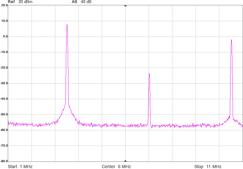
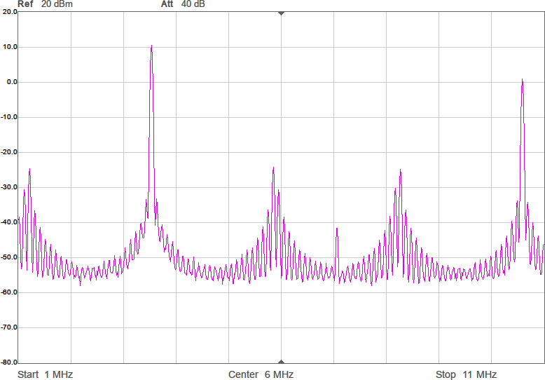
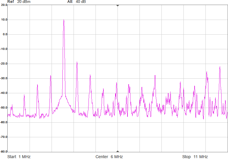
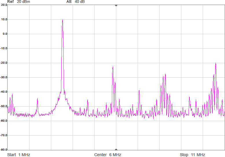
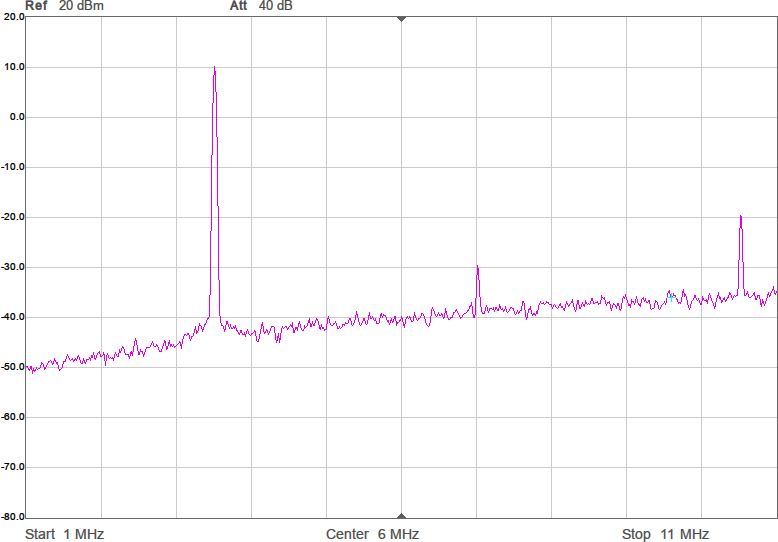
Utöver de harmoniska övertonerna vid multiplar av grundfrekvensen uppstår oftast en mängd spurioser i spektrumet eftersom bråktalsdelaren hoppar mellan olika heltal för att i medeltal hamna rätt. Exakt var spurioserna hamnar och hur starka de blir är olika för olika delarvärden. Figur 2a-d visar spektrum för några olika sändarfrekvenser vid 200 MHz processorklocka. De två renaste spektrumen har delare som är 28,5 respektive 28,0. Grundtonen är den högsta toppen medan tredje övertonen, HD3, ligger nära högra kanten. Andra övertonen, HD2, är bara signifikant i första spektrumet där delaren är 28,5.
Figur 2a. Ofiltrerat spektrum för 3 508 772 Hz vid 200 MHz processorklocka och klockdelare till PIO. Frekvensområdet är från 1 MHz till 11 MHz.Figur 2b. Ofiltrerat spektrum för 3 530 000 Hz.Figur 2c. Ofiltrerat spektrum för 3 550 000 Hz.Figur 2d. Ofiltrerat spektrum för 3 571 429 Hz.
För att få en komplett sändare behövs ytterligare några detaljer:
Ett lågpass- eller bandpassfilter som tvättar bort övertonerna (speciellt den vid tre gånger grundfrekvensen som i sig själv bara är ca 9 dB svagare än grundtonen eftersom det handlar om en fyrkantsvåg),
en anpassning mot den nästan skrattretande korta antennen (30 cm är inte mycket att komma med på 80m-bandet),
ytterligare lite programkod för att sända önskad morsekod och kanske lyssna på några knappar som väljer frekvens, rävnummer och morsetakt,
tre AA-batterier eller en LiPo-cell för att driva det hela och
en liten låda för väderskydd.
Ungefär här kunde artikeln vara slut, men jag hade ett par idéer om förbättringar som sedan började föröka sig…
Förbättringar som rör mjukvaran gör ju inte sändaren svårare eller dyrare att bygga, bara utvecklingstiden för programvaran längre och programkoden krångligare. Så låt oss se om det finns något att göra på främst mjukvarusidan.
Förberäknad vågform
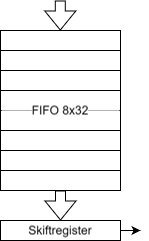
Efter lite googlande hittade jag [2] som är en mer komplett sändare byggd runt en RP2040. Den klarar AM, FM och SSB, delvis tack vare en extern modulator. Med små förändringar i koden skulle den även klara CW. En idé i denna lösning som jag gillade var att den använder en PIO på ett annat sätt. Istället för att ha ett PIO-program som autonomt växlar mellan etta och nolla på en utgång så matar huvudprogrammet i processorn ettor och nollor till PIO:n som sedan skickas ut i full fart. PIO:n har nämligen ett FIFO-minne på åtta ord om 32 bitar som kan fyllas på från processorn. På utgången av FIFO:t finns ett 32-bitars skiftregister och det finns en praktisk PIO-assemblerinstruktion som tar en bit från skiftregistret och skickar ut på en av processorns pinnar. När skiftregistret är tomt laddas det med ett nytt ord från FIFO:t. Se Figur 3.
Figur 3. Ett FIFO med 8 st 32-bitar breda ord samt ett skiftregister hör till varje tillståndsmaskin i en PIO.
Det nya och väldigt korta PIO-programmet ser ut så här:
.wrap_target
   out   pins, 1  ; Shift out one bit
.wrap
Även detta program loopar hela tiden, så varje klockcykel körs instruktionen som skiftar ut en bit från skiftregistret till en pinne.
Via DMA (direct memory access) kan man fylla på med data i FIFO:t när det finns plats ledigt utan att alls belasta själva huvudprocessorn. Så genom att i förväg räkna ut hur en fyrkantsvåg ska se ut för att skapa önskad frekvens, lägga fyrkantsvågen på något ställe i minnet och sätta upp DMA och PIO så att datat i denna minnesbuffert upprepat pumpas ut till PIO:n i den takt det förbrukas så skapar man alltså en fyrkantsvåg med önskad frekvens. I detta fall kör man PIO:n med fulla processorklockan.
Vad är då fördelen med detta över den första och betydligt enklare lösningen som inte involverade några minnesbuffertar och DMA? Det blir väl en fyrkantsvåg i båda fallen med ungefär önskad frekvens? Jo, en poäng här är att man kan approximera önskad frekvens mer noggrant. Det man måste göra för att uppnå det är att välja längden på minnesbufferten smart. Den består av 32-bitarsord och innehållet i ett ord förbrukas alltså under 32 processorklockcykler. Eftersom samma sekvens spelas upp om och om igen är det viktigt att bufferten innehåller ett helt antal perioder av vågformen man vill skapa så att man inte får ett fult fashopp när man börjar om från början av bufferten. Antalet 32-bitarsord i bufferten är en fri parameter, så beroende på vilken frekvens man vill sända så kan man välja en lämplig buffertlängd för att det ska gå jämnt upp med ett heltal perioder i vågformen.
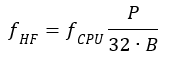
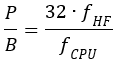
Om fCPU är processorfrekvensen, fHF är önskad bärvågsfrekvens, B är antalet 32-bitarsord i bufferten och P är antal perioder av vågformen som bufferten innehåller vill man alltså att B och P ska uppfylla:
Eller:
RP2040 har ganska mycket minne för att vara en mikrokontroller, 264 kB, dvs över 65 000 st 32-bitarsord. Om vi begränsar oss till exempelvis 10 000 ord i bufferten kan B alltså vara ett tal mellan 1 och 10 000. För varje B finns ett P som gör att vi hamnar närmast den fHF vi vill ha med just det valet av B och för något B hamnar vi närmast av alla. Det vore lätt att gå igenom alla B, räkna ut bästa P och komma ihåg den hittills bästa kombinationen av B och P. Med ”bara” 10 000 som största värde på B går det dessutom ganska fort. Men varför göra det enkelt när man kan göra det bättre? I samband med att jag skrev mjukvara till mina pejlmottagare där en Si5351 används som lokaloscillator stötte jag på ett liknande problem där motsvarigheten till B är över en miljon vilket gör att testande av alla kombinationer skulle ta opraktiskt lång tid. Så då utvecklade jag en algoritm som mycket snabbare hittar fram till bästa bråktalsapproximation av ett tal när nämnaren är begränsad. Den bygger på något som kallas för Farey-sekvenser och den intresserade kan läsa mer detaljer om hur det fungerar på min blogg [3]. Denna färdiga lösning kan man återanvända även här för att snabbt hitta bästa P och B givet fCPU, maximalt B och önskad fHF.
Med tekniken att pumpa ut data från en färdiguträknad buffert som är upp till 10 000 ord lång får man en betydligt finare frekvensupplösning. De möjliga delningsfaktorerna är inte likformigt fördelade och det visar sig att det finns ett par specialfall där maximala felet för frekvenser mellan 3,5 och 3,6 MHz är ca 45 Hz om man klockar processorn med 200 MHz, men i de allra flesta fall blir frekvensfelet mycket mindre än 1 Hz. För multiplar av 1 kHz blir felet 0 Hz. Man använder då som mest B = 6250 ord, vilket ger fHF = P∙1000 Hz. Om man nöjer sig med multiplar av 10 kHz kan man minska buffertlängden till 625 ord utan att få något avrundningsfel. Toleransen hos processorns kristall snarare än själva syntesmetoden avgör därmed noggrannheten i den skapade frekvensen.
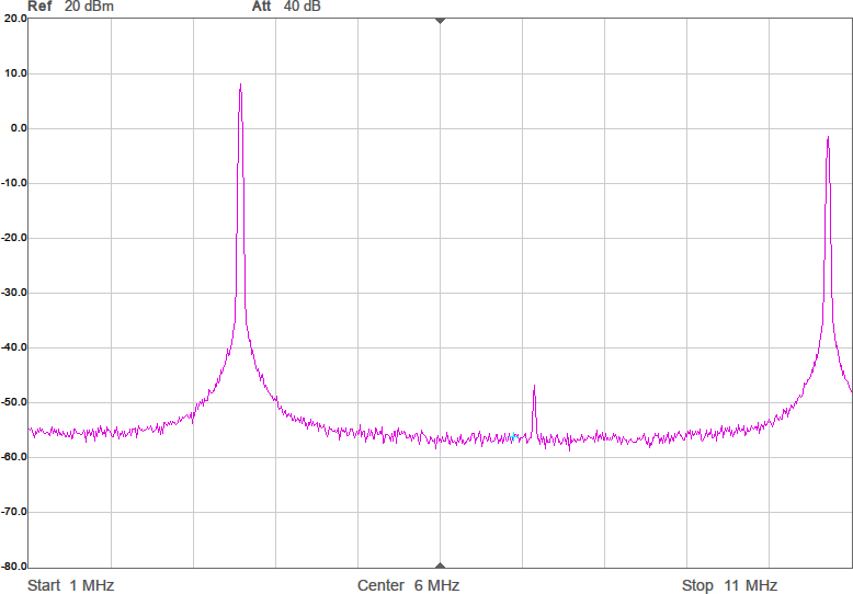
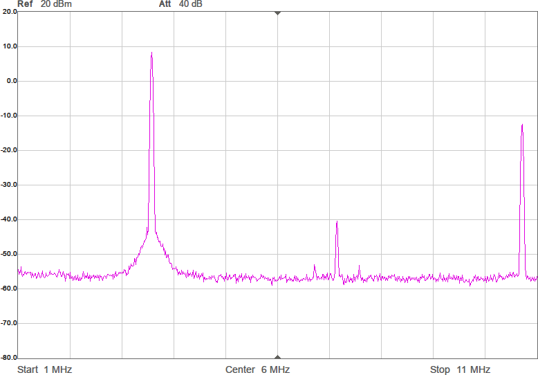
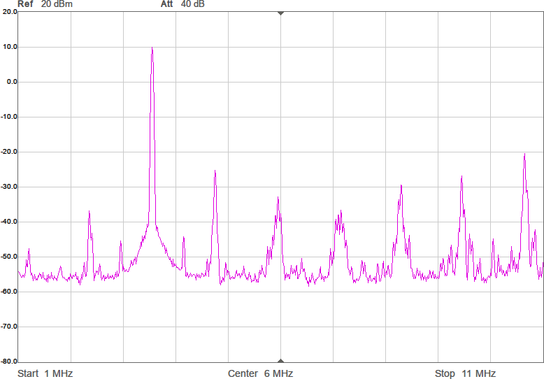
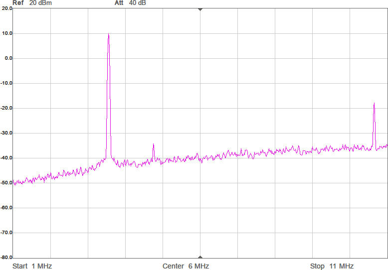
Figur 4 visar hur några spektrum blir med denna metod. Målfrekvenserna är desamma som i Figur 2. Som synes är det inte någon större skillnad på spektrumen jämfört med den tidigare metoden, vilket är förväntat eftersom det i båda fallen handlar om rena fyrkantsvågor som bara kan byta nivå var femte nanosekund (eftersom klockfrekvensen är 200 MHz).
Figur 4a. Ofiltrerat spektrum för 3 508 772 Hz vid 200 MHz processorklocka och förberäknad fyrkantsvåg. Frekvensområdet är från 1 MHz till 11 MHz.Figur 4b. Ofiltrerat spektrum för 3 530 000 Hz.Figur 4c. Ofiltrerat spektrum för 3 550 000 Hz.Figur 4d. Ofiltrerat spektrum för 3 571 429 Hz.
Inte så viktig förbättring kanske, men det är lite trevligt att ha större frihet att välja frekvens. Man skulle också kunna använda denna frihet för att kompensera för toleransen hos klockkristallen hos processorn om man gillar att finlira med sådant och bemödar sig att mäta upp verklig frekvens vid den temperatur som sändaren ska arbeta i. Den stora vinningen visar sig dock vara själva metoden att pumpa ut förberäknad data i full processorklocktakt till en pinne på processorn, för vi kan göra mer med denna metod.
Sigma-delta
När vågformen är beräknad i förväg kan vi lämna enkla fyrkantsvågor och ge oss in på något mer kraftfullt och lite mer komplicerat. Sigma-delta-modulering används ofta i audiosammanhang för att med ganska enkel och mestadels digital hårdvara skapa analog-till-digital (AD) och digital-till-analog (DA) -omvandlare med mycket hög upplösning och dynamik; ofta 24 bitar eller mer.
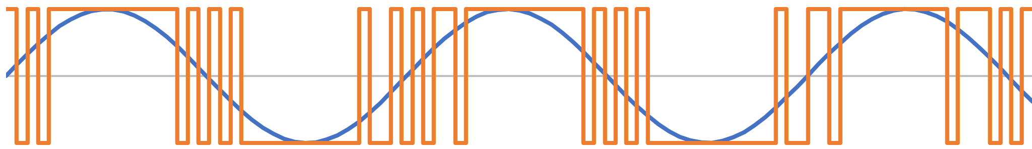
Principen för en sigma-delta DA-omvandlare bygger på att man håller reda på felet som skapas när man trösklar vågformen (t.ex. när man avgör om sinuskurvan ligger över eller under nollstrecket och väljer om utgången ska vara hög eller låg) och tar med det i beräkningen när man vid nästa klockcykel åter ska bestämma om utgången ska vara hög eller låg. För att resultatet ska bli bra krävs att klocktakten är många gånger högre än den frekvens man vill skapa. Resultatet är att utgången hoppar snabbt mellan hög och låg när vågformen man försöker efterlikna är nära noll, medan den ligger mer stabilt hög eller låg när vågformen är nära en topp eller dal. Figur 5 visar hur det kan se ut.
Figur 5. Sigma-delta-modulering av en sinusvåg.
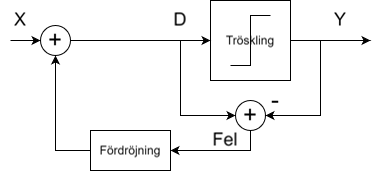
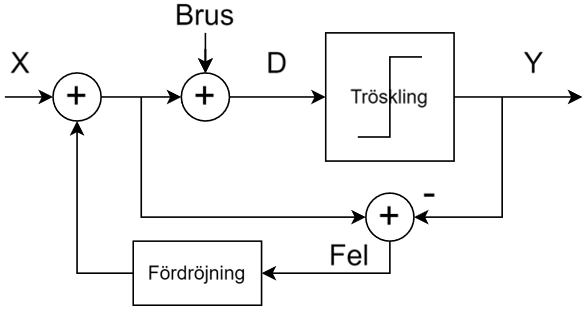
I Figur 6 visas hur blockschemat för moduleringen ser ut. Signalen man vill modulera (sinusvågen) kommer in från vänster vid X. Det tidigare felet adderas och resultatet D trösklas för att skapa utsignalen Y. Skillnaden mellan D och Y, dvs det fel som uppstår vid trösklingen, räknas ut och påförs insignalen vid nästa klockcykel.
Figur 6. Blockschema för en sigma-delta-modulator.
Ser man på det spektralt visar det sig att sigma-delta-moduleringen gör att kvantiseringsbruset trycks upp till högre frekvenser och därmed blir lättare att filtrera bort. Man eliminerar också mycket av de harmoniska övertonerna. En ren fyrkantsvåg har en överton vid tre gånger grundfrekvensen (HD3) som är endast 9 dB lägre än grundtonen, men med sigma-delta-modulering kan den tryckas ned betydligt och minska kraven på det analoga filtret före antennen.
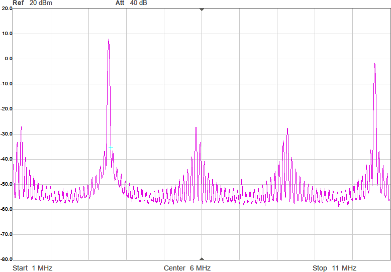
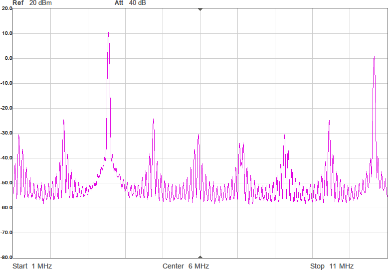
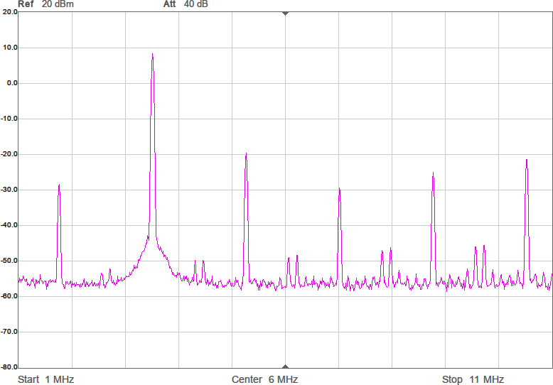
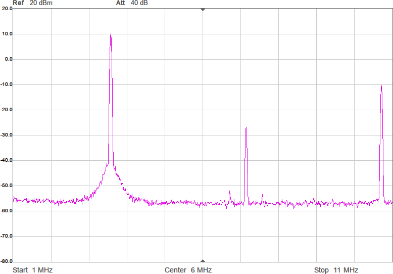
Sagt och gjort. Efter lite (eller ganska mycket…) felsökande fick jag till programkod som räknar ut sigma-delta-modulerade vågformer. Figur 7 visar vågformen och Figur 8 spektrumen med denna metod. Tidigare var HD3 ca 9 dB under grundtonen, men nu är den i värsta fallet ca 20 dB under och i andra fall 30–40 dB under. En hygglig förbättring alltså.
Figur 7. Vågform vid sigma-delta-modulering av en sinusvåg.Figur 8a. Ofiltrerat spektrum för 3 508 772 Hz vid 200 MHz processorklocka och förberäknad sigma-deltamodulerad vågform. Frekvensområdet är från 1 MHz till 11 MHz.Figur 8b. Ofiltrerat spektrum för 3 530 000 Hz.Figur 8c. Ofiltrerat spektrum för 3 550 000 Hz.Figur 8d. Ofiltrerat spektrum för 3 571 429 Hz.
Differentiell utgång
Nu är det väl ändå så bra det kan bli? Vi har ju uppnått väldigt god frekvensupplösning och nedtryckta övertoner, trots att vi bara använder en mikrokontroller utan särskilt stöd för att agera HF-generator. Inte riktigt. Ytterligare en idé jag fick var att använda inte en utgång, utan två, som jobbar i motfas. En fördel med detta är att man kan få ut högre effekt eftersom två utgångar (två ”slutsteg”) hjälps åt. En annan är att man borde undertrycka andra ordningens distorsion som kommer av att pinnarna är olika starka när de driver en hög nivå jämfört med när de driver en låg. En tredje och mindre viktig fördel är att man minskar den högfrekventa strömmen på matningen till processorn eftersom man drar ungefär samma ström hela tiden. Därmed minskar ripplet på processorns matning (vilket i det här fallet knappast är särskilt viktigt).
För att skapa en differentiell signal gäller det att skicka ut en nolla på den ena utgången samtidigt som det skickas ut en etta på den andra och tvärt om. Det kräver dubbelt så mycket förberäknad data eftersom det inte finns något sätt att få en PIO att invertera en signal utan att det tar extra klockcykler. Om man använder samma mängd minne för buffertarna så får man med denna metod alltså bara hälften så många sampel och därmed lite sämre frekvensupplösning. En fin finess är att en PIO kan skicka ut mer än en bit per klockcykel från skiftregistret till olika pinnar. Så genom att lägga udda bitar med omvänd polaritet mot jämna och skriva om PIO-programmet att skicka ut två bitar per klockcykel istället för en så kan man skapa en differentiell signal. Enda ändringen i PIO-programmet är att ettan blir en tvåa för att skifta ut två bitar per klockcykel:
.wrap_target
   out   pins, 2  ; Shift out two bits, one to each pin
.wrap
Vilka pinnar som berörs ställs in i förväg genom registerskrivningar till PIO:n.
En nackdel är alltså att det går åt dubbelt så mycket minne för samma längd på sekvensen och en annan är att DMA:n måste jobba dubbelt så fort, men det är väldigt akademiska invändningar eftersom det ändå finns mer kapacitet i form av minne och DMA-bandbredd än man kan tänkas behöva i den här tillämpningen.
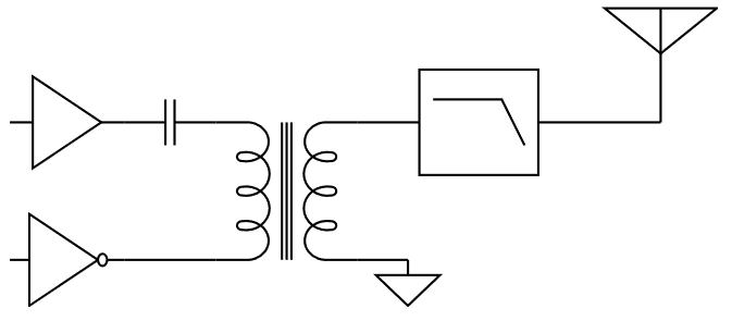
För att skapa signalen till antennen behövs nu en balun, t.ex. i form av en transformator vars primärlindning kopplas mellan pinnarna som drivs i motfas med varandra. En kondensator i serie är också en god idé för att hindra strömrusning om pinnarna av någon anledning skulle sluta ändra nivå hela tiden. Se Figur 9.
Figur 9. En transformator med kondensator i serie med primärlindningen agerar balun och omvandlar den differentiella signalen från två processorutgångar till en signal som kan driva antennen.
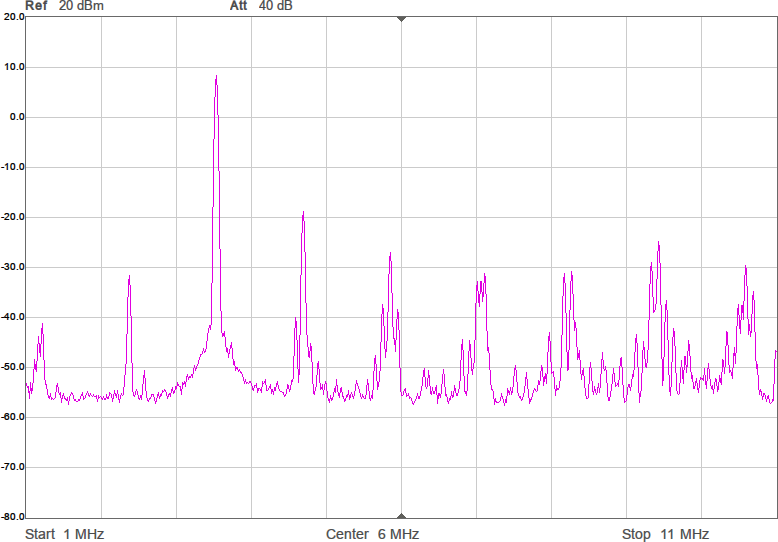
I Figur 10 visas de nya spektrumen. Förutom att signalnivån är någon dB högre har inte mycket hänt. Men man kan notera att HD2 av någon anledning inte blev lägre utan högre i sista spektrumet. Oklart varför.
Figur 10a. Ofiltrerat spektrum för 3 508 772 Hz vid 200 MHz processorklocka och differentiell förberäknad sigma-deltamodulerad vågform. Frekvensområdet är från 1 MHz till 11 MHz.Figur 10b. Ofiltrerat spektrum för 3 530 000 Hz.Figur 10c. Ofiltrerat spektrum för 3 550 000 Hz.Figur 10d. Ofiltrerat spektrum för 3 571 429 Hz.
Trenivåers kvantisering
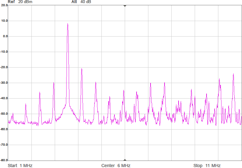
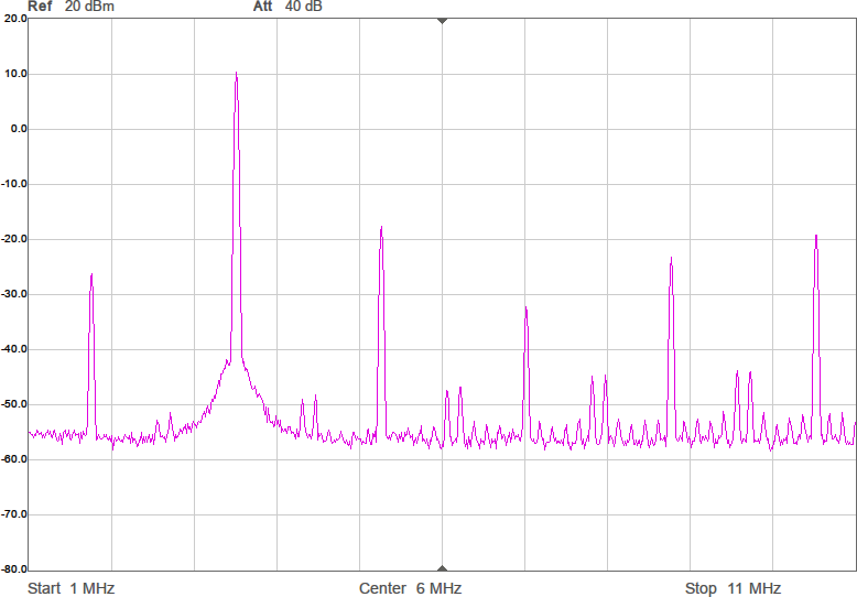
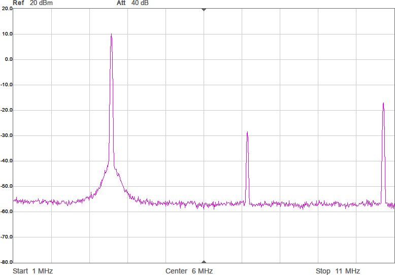
När man har en differentiell signal mellan två digitala utgångar finns det fyra möjligheter; låg-hög och hög-låg har vi utnyttjat, men pinnarna skulle även kunna ha nivåerna låg-låg eller hög-hög. I de två senare fallen blir ju signalen, som är skillnaden mellan utgångarna, noll, men detta är också användbart. Genom att tillåta dessa tillstånd kan vi gå ifrån att kvantisera signalen till ett av två möjliga lägen, som vi kan kalla +1 och -1, till att ha tre nivåer som vi kan kalla +1, 0 och -1. Kvantiseringen blir alltså mindre grov, vilket ytterligare förbättrar spektrumet genom att en del spurioser undertrycks. Figur 11 visar vågformen och Figur 12 spektrumen efter att trenivåers kvantisering införts.
Figur 11. Vågform vid sigma-delta-modulering med trenivåers kvantisering.Figur 12a. Ofiltrerat spektrum för 3 508 772 Hz vid trenivåers kvantisering. En del av spurioserna har blivit betydligt lägre jämfört med tvånivåers.Figur 12b. Ofiltrerat spektrum för 3 530 000 Hz.Figur 12c. Ofiltrerat spektrum för 3 550 000 Hz.Figur 12d. Ofiltrerat spektrum för 3 571 429 Hz.
Dithering
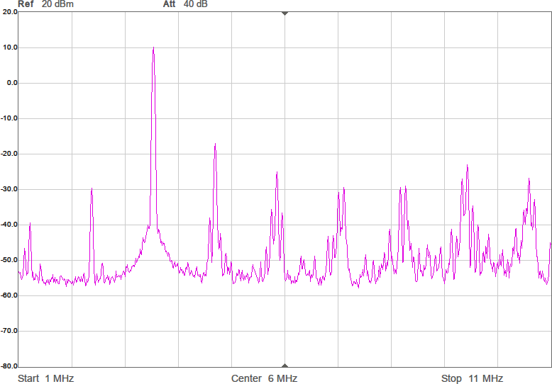
Är vi klara ännu? Nej! Det finns mer att göra. Som synes finns fortfarande ett antal spurioser här och var i spektrumen. Detta är alltså inte övertoner till grundtonen, utan skapas genom en komplicerad interaktion mellan tonen man vill skapa, den begränsade samplingsfrekvensen och kvantiseringen. Skräp som är ihopsamlat till en specifik frekvens är värre än om energin i skräpet vore utspridd över ett bredare frekvensområde eftersom det lättare kan störa ut en smalbandig mottagare. Och spurioser nära grundtonen är svårare att filtrera bort än spurioser på större avstånd. Som tur är finns en teknik att sprida ut dessa toner. Tekniken kallas ”dithering” och går ut på att lägga till brus innan man kvantiserar signalen. Ett blockschema som visar hur detta brus läggs till i sigma-delta-modulatorn visas i Figur 13. Som synes läggs bruset till precis före kvantiseringen och felet som det introducerar fångas alltså upp av den vanliga felåterkopplingen.
Figur 13. Brus läggs till, ”dithering”, vilket minskar övertonerna och sprider ut spurioserna.
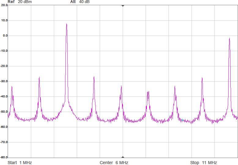
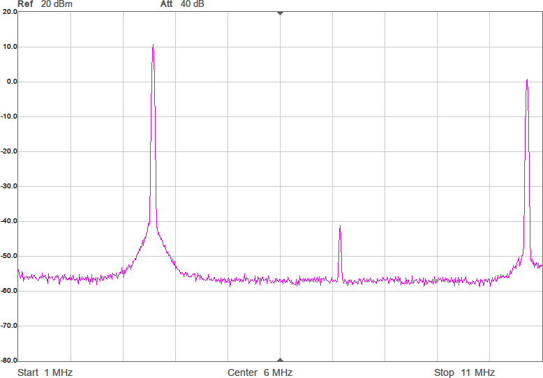
Bruset är en serie pseudoslumptal och man kan laborera med hur stora de ska vara samt vilken spektral- och amplitudfördelning de ska ha. En enkel lösning som verkar fungera någorlunda bra är att ha likformigt fördelat brus med samma maxamplitud som på sinusvågen. Spektrum efter tillägget av dithering visas i Figur 14. Som synes har det dykt upp ett brusgolv som blir högre vid högre frekvenser samtidigt som spurioserna sjunkit. Den högsta spuriosen var tidigare den vid ungefär 5,7 MHz vid 3,55 MHz grundton. Nu har denna ton sjunkit med nästan 10 dB.
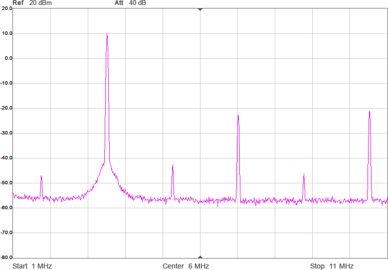
Figur 14a. Ofiltrerat spektrum för 3 508 772 Hz vid 200 MHz processorklocka, dithering, differentiell förberäknad trenivåers sigma-deltamodulerad vågform. Frekvensområdet är från 1 MHz till 11 MHz.Figur 14b. Ofiltrerat spektrum för 3 530 000 Hz.Figur 14c. Ofiltrerat spektrum för 3 550 000 Hz.Figur 14d. Ofiltrerat spektrum för 3 571 429 Hz.
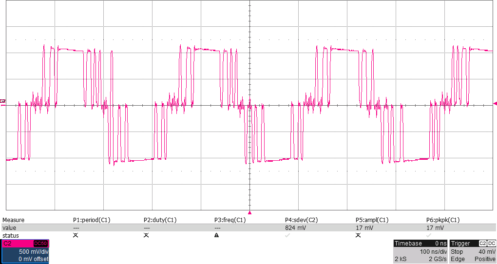
I tidsdomänen ser vågformen lite stökigare ut än tidigare på grund av det pålagda bruset, vilket visas i Figur 15.
Figur 15. Vågform vid sigma-delta-modulering med trenivåers kvantisering och dithering.
Minskning av nyckelknäppar/splatter
Varför sluta här? En inte så elegant sak med att slå av och på bärvågen abrupt är att man orsakar nyckelknäppar (splatter), dvs skapar störningar i närheten av den frekvens man egentligen har tänkt hålla sig till. Lösningen är att göra övergångarna mellan tystnad och sändning mjukare, dvs att mer gradvis slå av eller på bärvågen. Eftersom vi spelar upp förberäknade vågformer kan vi beräkna sådana som mjukt ordnar en sådan övergång. Det äter upp mer minne och här blir det viktigare att använda tillräckligt långa buffrar för att övergången ska ta tillräckligt lång tid för att väsentligt minska nyckelknäpparna. Föra att inte komplicera programkoden alltför mycket så går vi från att ha en enda buffert med bärvågen till fyra lika långa buffertar för vardera upprampning, bärvåg, nedrampning respektive tystnad. Det går alltså åt fyra gånger så mycket minne (åtta om vi jämför med innan vi gjorde signalen differentiell) och nu börjar vi känna av att minnet trots allt är begränsat.
Liksom tidigare är det DMA som skyfflar data från buffertarna till PIO:n, men eftersom vi nu inte alltid ska upprepa innehållet i samma buffert om och om igen så införs ett interrupt (avbrottsrutin) som anropas varje gång en buffert har spelats färdigt. Om huvudprogrammet som sköter morsesignaleringen exempelvis satt en flagga som säger att det är dags att sluta sända får interruptrutinen styra om så att nästa buffert är nedrampningsbufferten som sedan följs av bufferten med tystnad.
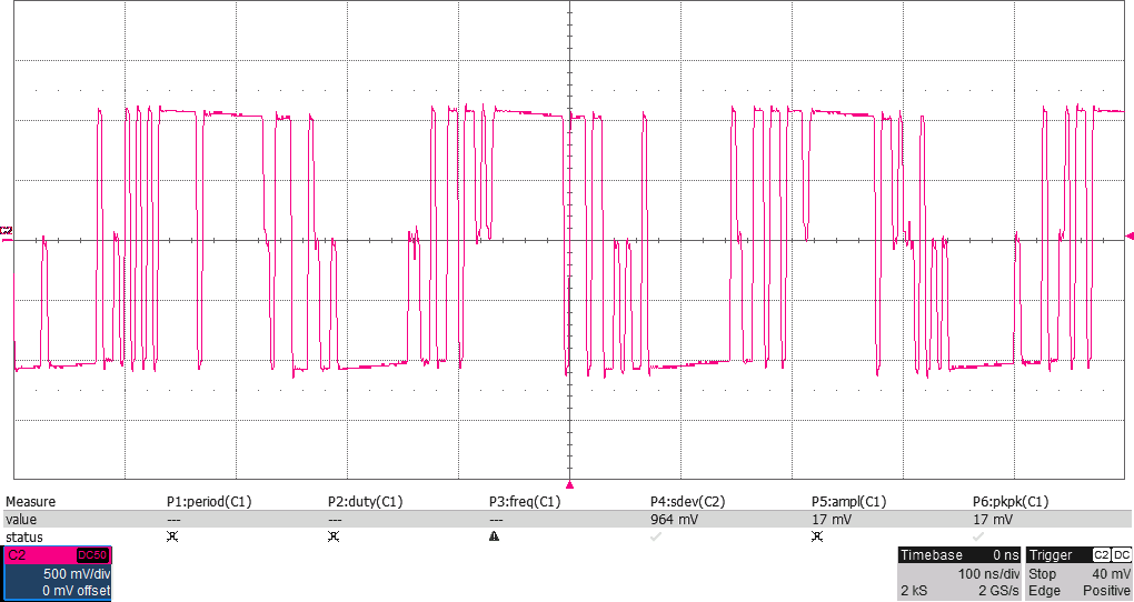
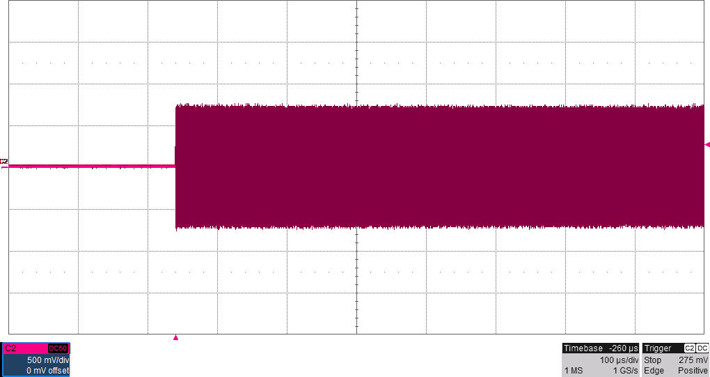
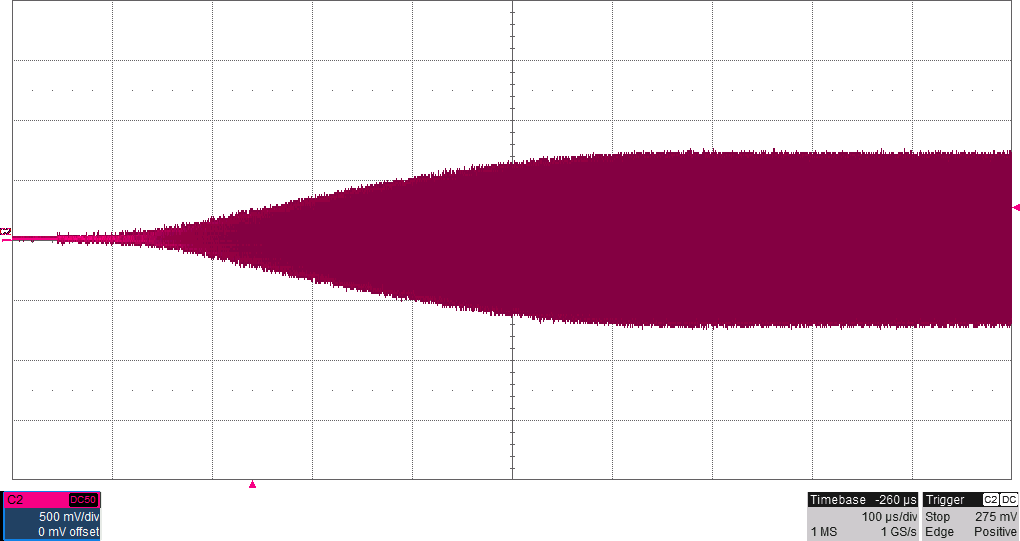
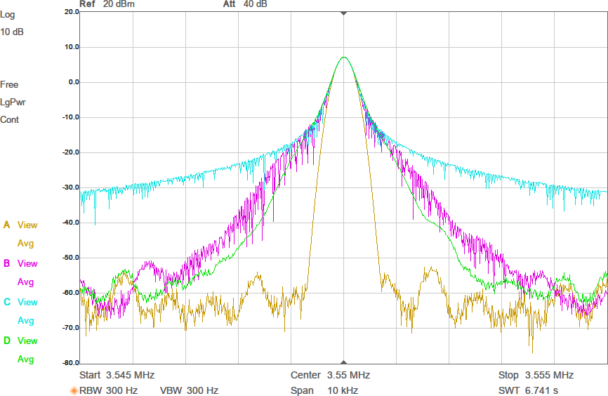
Figur 16 visar hur bärvågen ser ut efter lågpassfiltrering i samband med abrupt respektive mjuk upprampning. I Figur 17 jämförs spektrum mellan konstant bärvåg, mjuka övergångar med 15 000 ord långa buffertar (äter upp nästan allt minne), 10 000 ord långa buffertar, respektive abrupta övergångar. Spektrumen samlades in genom att köra hög morsetakt (många nyckelknäppar per sekund) och använda ”max hold” i spektrumanalysatorn i någon minut för att fånga maximal amplitud vid varje frekvens. Som synes sjunker störningarna i närheten av bärvågen när man har de mjukare ramperna och längre övergångar ger därmed som väntat minskade nyckelknäppar i grannkanalerna.
Figur 16a. Abrupt upprampning av bärvågen.Figur 16b. Mjuk upprampning av bärvågen.Figur 17. 10 kHz brett spektrum som visar nyckelknäppar. A gul: konstant signal (inga knäppar), D grön, mjuka övergångar med 15 000 ord buffertlängd, B lila: mjuka övergångar med 10 000 ord buffertlängd, C cyan: abrupta övergångar.
Byte av processor
Med tanke på de ökade minneskraven kan det vara värt att fundera på att använda den nyare RP2350, monterad på kortet Raspberry Pi Pico 2, som har ungefär dubbelt så mycket minne som RP2040. RP2350 har dessutom inbyggd flyttalsprocessor, så beräkningen av innehållet i buffertarna baserat på frekvens, dithering och nyckelknäppsminimering som tar 16 sekunder på en RP2040 (när buffertlängden är 15 000 ord) minskar till under tre sekunder. En viktigare fördel är att strömförbrukningen är lägre på RP2350. Vid 200 MHz processorklocka och konstant sändning uppmätte jag en minskning av strömmen på 5-V-matningen från 50,5 mA till 38,6 mA när jag bytte till det nyare processorkortet. När sändning inte sker drar Pi Pico 32 mA medan Pi Pico 2 drar 21; återigen vid 200 MHz processorklocka. Det något högre priset på en Pi Pico 2 uppvägs mer än väl av den lägre strömförbrukningen och högre prestandan.
Kod
Den som vill experimentera vidare med metoderna som jag beskrivit i den här artikeln kan ladda ned koden jag skrivit för det hela på [4]. Det är inte kod som är tänkt att användas utan ändringar i en foxoringsändare, utan den erbjuder ett interaktivt sätt att via kommandon man skriver in via ett terminalfönster experimentera med de olika moderna som beskrivits ovan. När strömmen slås på så börjar den snart sända ut signaler som från en foxoringsändare, men det krävs ändringar i koden eller kommandon via serieporten (över USB) för att välja frekvens, kodtakt eller rävnummer.
Del 2
Figur 1 visar en spretig prototyp med RF-delarna som behövs för en sändare. I del 2 av artikeln beskrivs framtagandet av de analoga delarna, bygge på ett riktigt kretskort tillsammans med lite DIP-switchar och en (valfri) display samt komplettering av koden så att det blir en välfungerande foxoringsändare.