Back in 2023, I published a 3D-printed tape measure Yagi antenna design för “fox hunting” on the 2m band (144 MHz). While the antenna worked (and still works) fine, I realized that it would be better to have the tape measure pieces mounted with the broadside towards the front rather than up. That way, they more gracefully bend when they hit branches and trees.
Another change I wanted to make was to the spools one can roll upp the antenna elements onto. They were previously designed to be printed as two separate pieces and glued together. While this makes the 3D printing easy without any need for supports, the gluing is a bit messy. I therefore wanted to come up with a design that does not require any gluing. This instead requires some support material, but by printing the clamp that goes around the spool “in place”, most of the supporting is done by the clamp.
Yet another novelty is that I wanted it to be possible to disassemble the antenna to make the pieces short enough to fit in a reasonably sized suitcase. I therefore cut the pipe at a location that ends up in the middle of the holder for the driven element and let the holder also clamp the two pieces of the pipe together.
Here is a link to a zip-file with the 3D models for printing:
Link to a zip-file with 3MF models of the parts:
Here is a drawing with dimensions:
The shortest element is the director (towards the main lobe of the antenna) while the longest is the reflector. The “driven” element, connected to the receiver, is the one in the middle.
According to YagiCAD, the radiation pattern of the antenna is as follows:
For the boom, I use a piece of 16 mm outside diameter PVC electrical conduit pipe (“VP-rör” in Swedish).
For the elements, I use 25 mm wide steel tape measure from Biltema, e.g. part number 16-2931.
Throughout the design, M3 screws and nuts are used to hold the pieces together. Stainless screws and nuts should ideally be used to prevent corrosion over time.
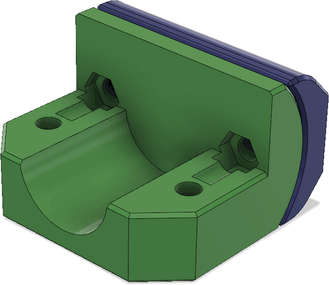
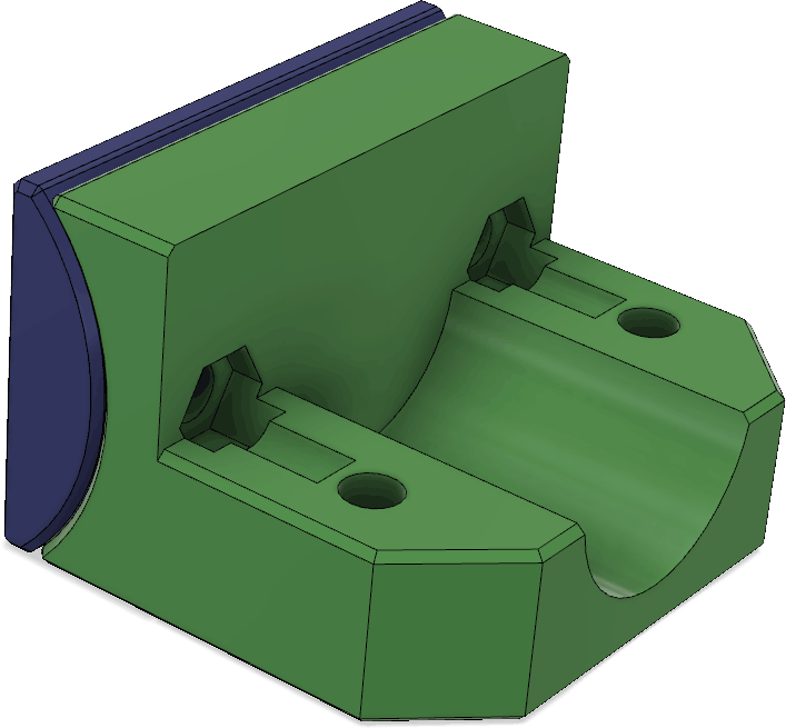
The front element (director) is held by these 3D printed pieces that clamp onto the pipe as well as to the tape measure:
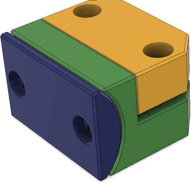
The rear element (reflector) is held by similar parts. The main difference is that the tape measure is reversed relative to the end of the pipe compared to how it is at the front . The reason is of course to hold the tape measure in the orientation that makes it bend most easily when one runs forward and it collides with some object.
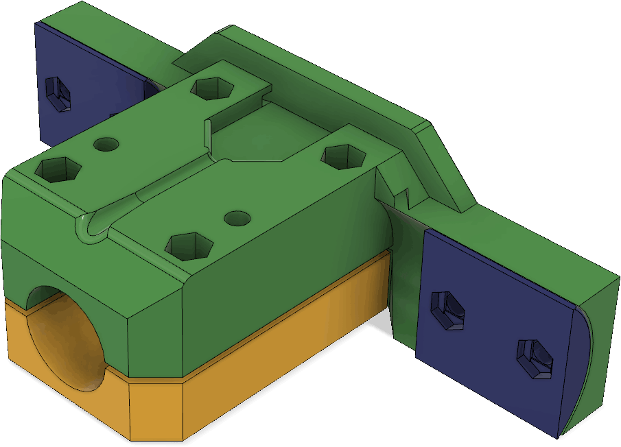
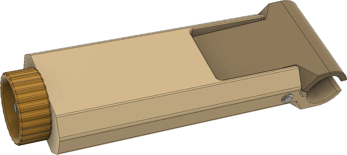
The parts holding the driven element are a little more complex:
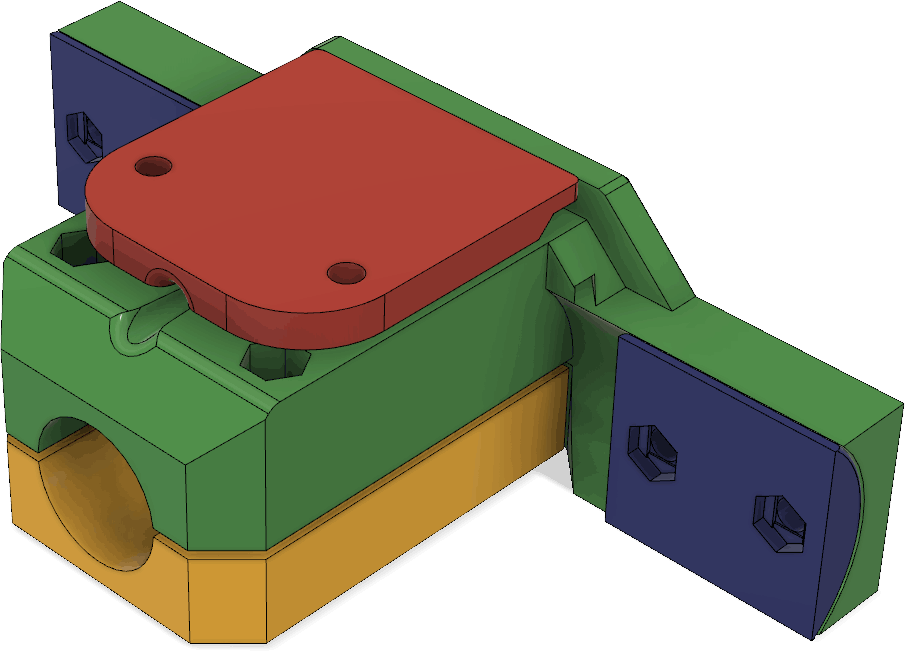
The red piece serves both as a clamp for the coax cable and as a cover to mechanically protect the connections between the coax and the wires leading to the antenna elements. Under it, there is a pocket for making those connections:
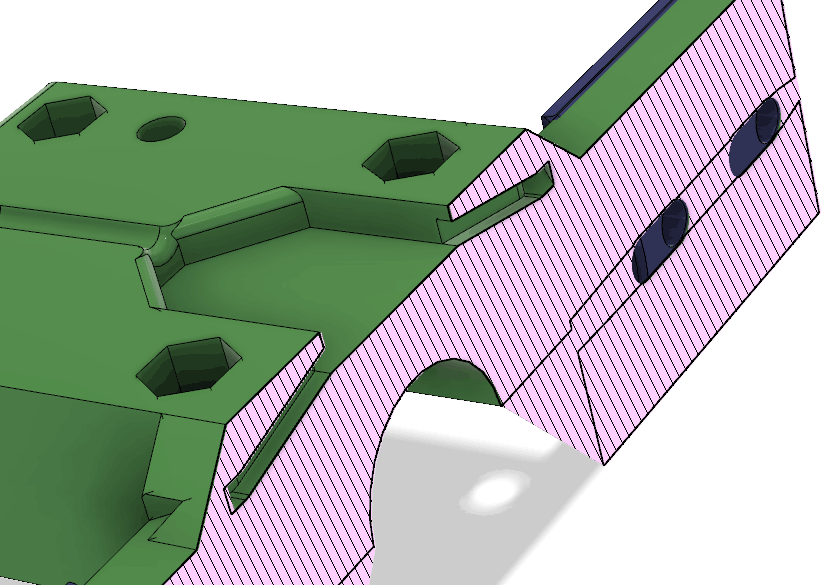
There are channels for routing the wires from the pocket to the antenna elements as can be seen in this cross section:
The coax (RG174) going into the pocket and connecting to the antenna elements may look like this with the cover/strain relief removed:
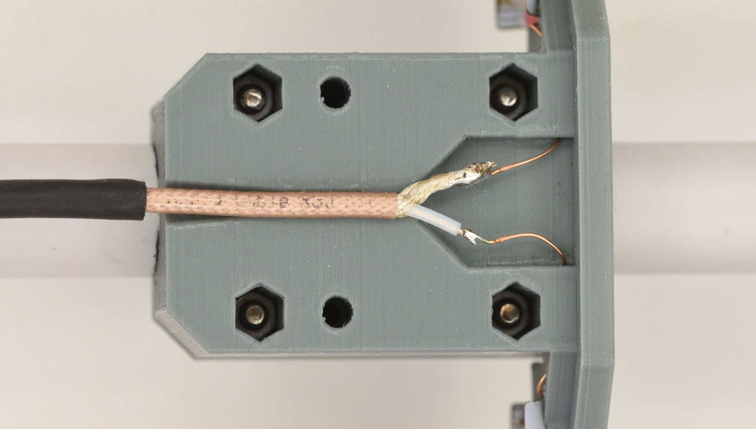
I did not use a balun between the differential antenna elements and the unbalanced coax, but it seems to work fine anyway. The pocket is otherwise big enough to fit a little PCB with a balun, or some other balun solution. Maybe I will try that in the future.
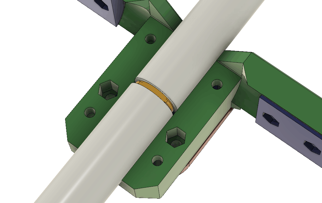
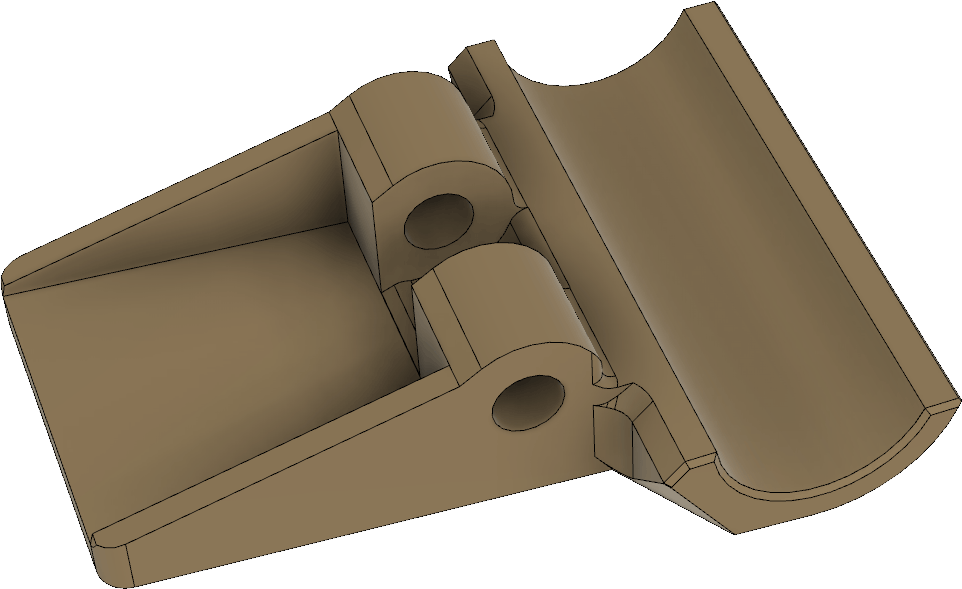
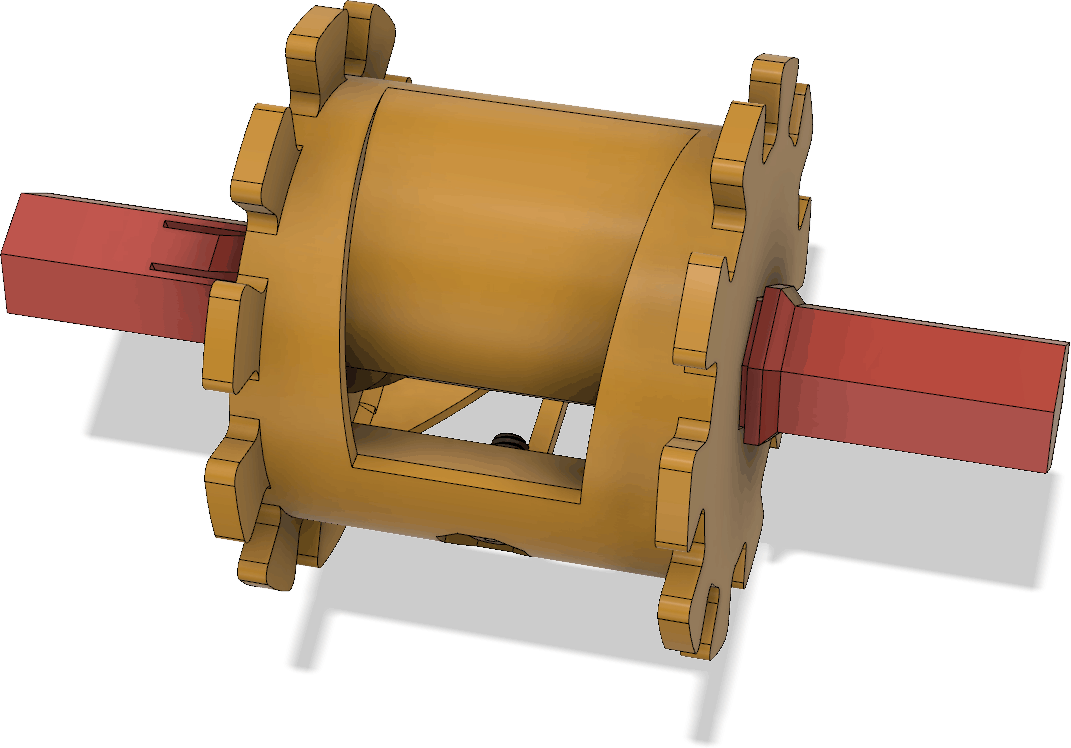
These parts serve double duty as they both hold the receiving antenna elements, but also can hold the boom together if it is split up into two pieces to allow it to be disassembled into two segments:
To reinforce the joint between the boom segments, there is a little plug with a ridge around the middle that fits into the two pipe sections:
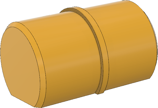
The flat part of this piece lets it be easily printed without supports. There is no need for it to be a complete cylinder.
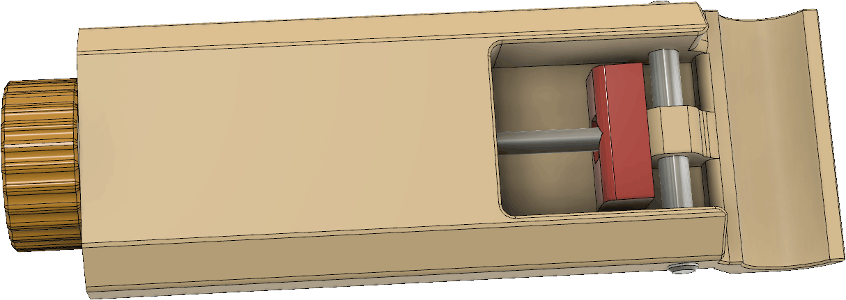
I also made some modifications to the handle. It is now a little simpler, perhaps lighter and the clamp pivots around a 5 mm steel pin. (An M5 screw might also work.) There is still a mechanism with a wedge pulled by a threaded M4 rod to tighten the grip around the pipe:
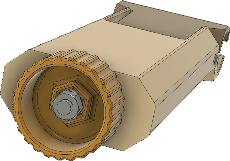
For the knob to hold on securely to the threaded M4 rod, two nuts should be tightened against each other inside the knob:
The grip around the pipe is however not as secure as one might hope. The pipe is slippery, so to avoid having the handle easily slip and rotate around the pipe while running, I made a little peg that can be glued onto the top of the pipe (preferably using epoxy). The gap in the handle clamp fits around the peg and prevents the handle from rotating. There are two holes in the peg where one can insert pieces av 3D filament to reinforce the glue joint. Corresponding holes obviously need to be drilled into the pipe as well.
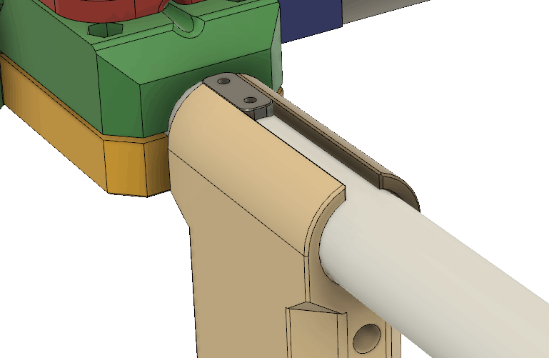
When the antenna is used, the handle is pushed forward so that the peg ends up in the gap and prevents the handle from rotating. During storage, the handle can be slid away from the peg and rotated to the side to make the antenna more compact.
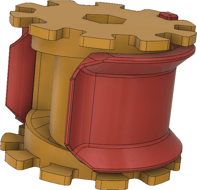
The spools and clamps that allow the tape measure elements to be rolled up for storage are perhaps the most complex parts in this design. As mentioned previously, they can now be printed as one piece, no glue required, but at the price of using supports during printing. So there is still some manual work to do to remove the supports, even if the messier gluing is avoided. By printing the clamp that keep the the tape measure from unrolling from the spool in place around the spool, it will serve as part of the supports and save some material and print time.
The spool and clamp together look like this:
Six sets of spools/clamps are needed for a complete antenna.
To help when rolling up the tape measure onto the spool, there is also a hexagonal pin that fits in the center hole of the spool:
Only one such pin is needed per antenna as it can be moved between the spools.
The short M2.5 screw that is used as a hook for the tip of the tape measure when rolling it up is barely visible above.
With supports (green), the spool and clamp may look like this in the 3D slicer:
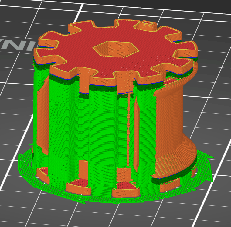
All other pieces print without support.
A spool in use (with the pin in place) is shown below:
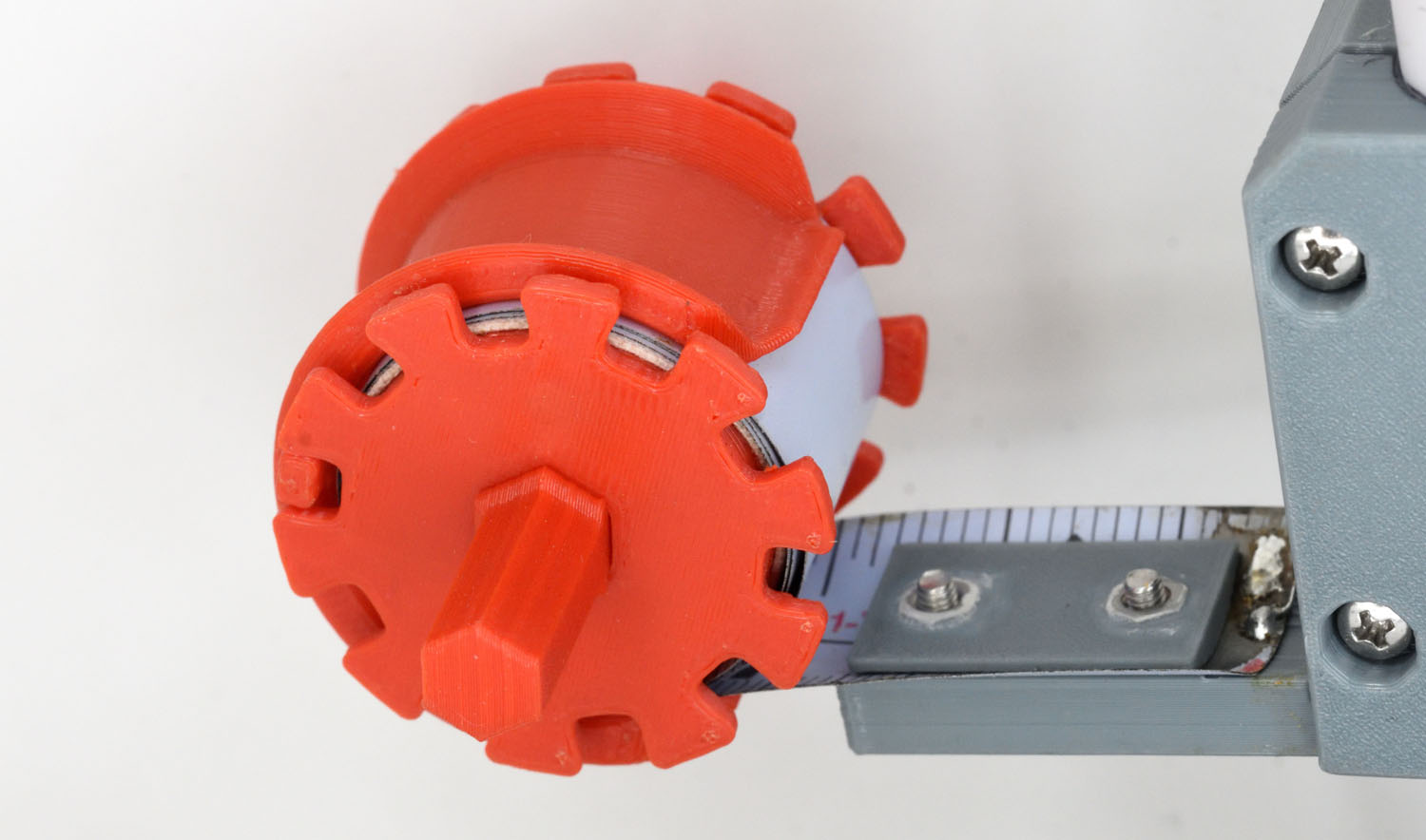
I printed the spools using red filament to make them more easy to spot in most environments and thus reduce the risk of losing them.
The tips of the tape measure elements need to be chamfered at a shallow angle to fit into the spools and a hole should be made near the tip to fit the M2.5 “hook” in the spools. The cut edges easily become very sharp, so to protect from injuries, they should be covered by sports tape:

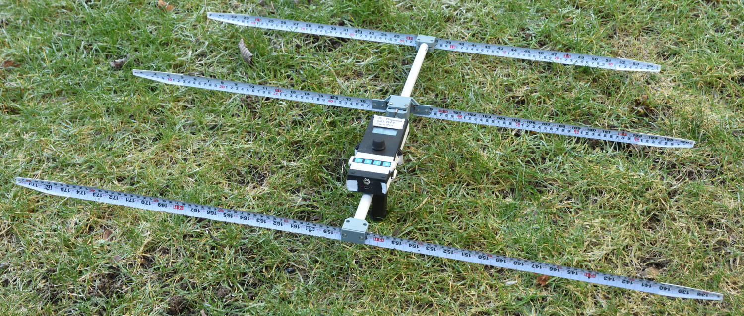
A photo of the entire antenna with a receiver in a box also attached to the boom is shown below.
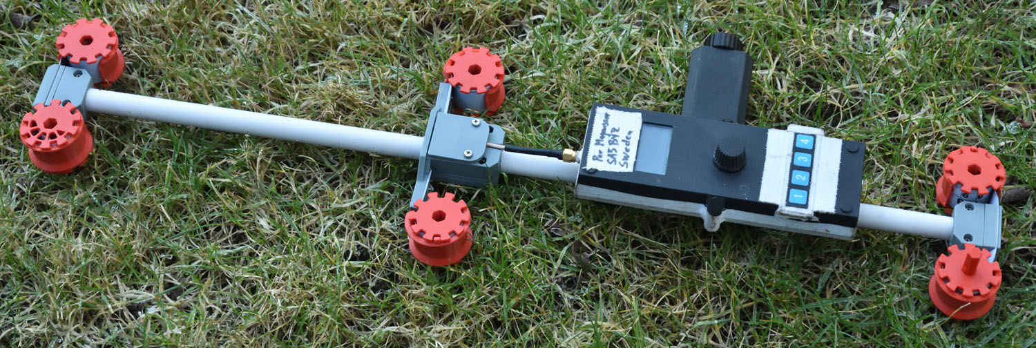
The receiver with the elements rolled up looks like this:
One thought on “Improved 2 m Fox Hunting Antenna”