By Per Magnusson, SA5BYZ
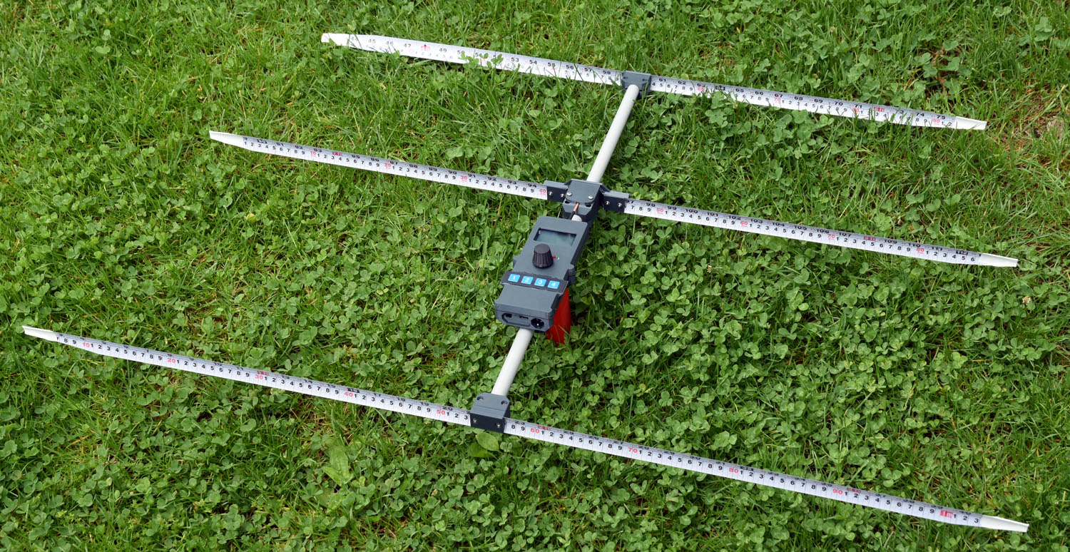
This is the first in a series of articles describing a 2 m (144 MHz) direction finding receiver for “fox hunting”. I have built a few of these for myself and for friends. The receivers have been used on events starting in 2025, including the ARDF World Championships in Lithuania. The antenna I have been using is a previously published tape measure Yagi. The antenna as well as the receiver uses many 3D-printed parts.
Article Parts
The receiver is described in the following articles:
- Part 1 – Overview (this article)
- Part 2 – RF board
- Part 3 – Processor board
- Part 4 – Other boards
- Part 5 – Mechanics
- Part 6 – Usage
- Antenna (published earlier)

Overview
The intention is to provide all the information and files necessary to understand and build the receiver, including schematics, PCB-files, BOM-lists, 3D-files and software. But be warned that the design is significantly more complex than most other published HAM DIY projects and requires advanced skills in soldering, assembly and perhaps debugging of hardware and software. If you build it and run into problems, there is no guarantee I am willing or have time to support you. Only try to build this if you are OK with this premise.
This receiver has a largely software defined radio architecture. The signal from the antenna is amplified or attenuated before being mixed down to a low IF (13 kHz) using an I/Q mixer. I and Q are then digitized with an audio codec. Suppression of the unwanted sideband as well as selection of IF bandwidth and AM detection is handled in software.
The software adds an audio RSSI tone to the signal which is helpful to more accurately find the direction in which the signal is strongest. A bonus with this scheme is that – in contrast to receivers that just demodulate the AM-signal – signal strength information is present also between the dits and dahs if the transmitter keeps the carrier on all the time during transmission. Some transmitters do this, while others do not.
The display shows the signal strength in (arbitrary) dB units, which helps estimating the distance to the transmitter. This reading is independent of the gain setting.

The local oscillator is an Si5351 PLL with a TCXO as reference, so frequency accuracy is very good. Several frequencies can be pre-programmed and quickly cycled between. Normally just one or two pre-programmed frequencies are required (foxes and beacon) at an event, but more may be useful at special events. The IF bandwidth can be selected between 21 kHz, 6 kHz and 3 kHz, which may be helpful when a transmitter is very weak or there is interference on nearby frequencies. Normally the 21 kHz bandwidth is used.
A 3.5 mm audio jack is provided to allow usage of standard headphones. A USB-C connector is used for charging the built-in LiPo battery as well as for firmware updates.
Overview of the electronics
The electronics is divided into several PCBs to make the design compact and light-weight:
- A 4-layer RF board with attenuator/amplifier, local oscillator, mixer, IF-filter and the IF amplifiers
- A 4-layer processor board with ADC, DAC, processor and interfaces to other boards
- A display board with the LCD
- A connector board with USB and headphone connectors
- A front panel board with interfaces to buttons, LEDs and a rotary encoder
- Possibly a little balun board at the antenna
The RF and processor boards contain many tiny surface-mount components that most people would find hard or impossible to assemble at home. I let JLCPCB take care of manufacturing of all the PCBs. I also let them assemble the (top sides) of the RF board and the processor board. The other boards contain much fewer components, but some are still tiny fine-pitch SMD parts, so you might want to let e.g. JLCPCB or PCBWay take care of those assemblies as well.
License
You may build this on a non-commercial basis for yourself and a few friends, up to five units in total. You are not allowed (without a further license agreement with me) to base commercially produced units on this design. The same disclaimers of warranty and limitations of liability as in sections 15 and 16 of the Gnu General Public License v3 applies. The software is covered by GPL v3.
I hope you find these articles informative and educational.