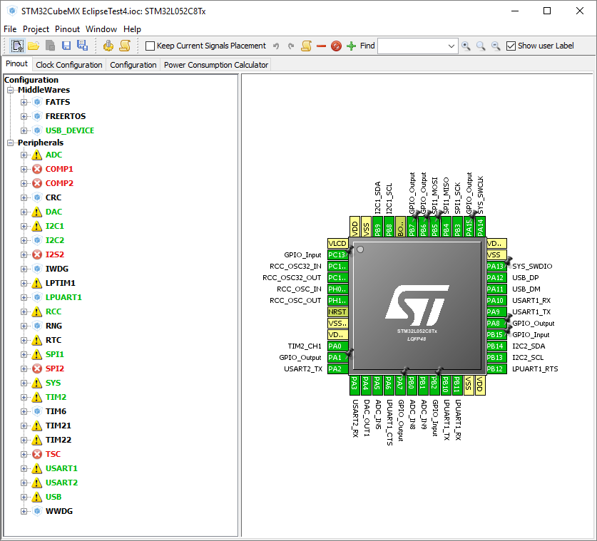
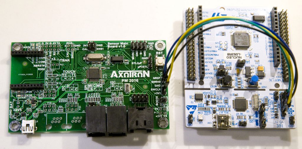
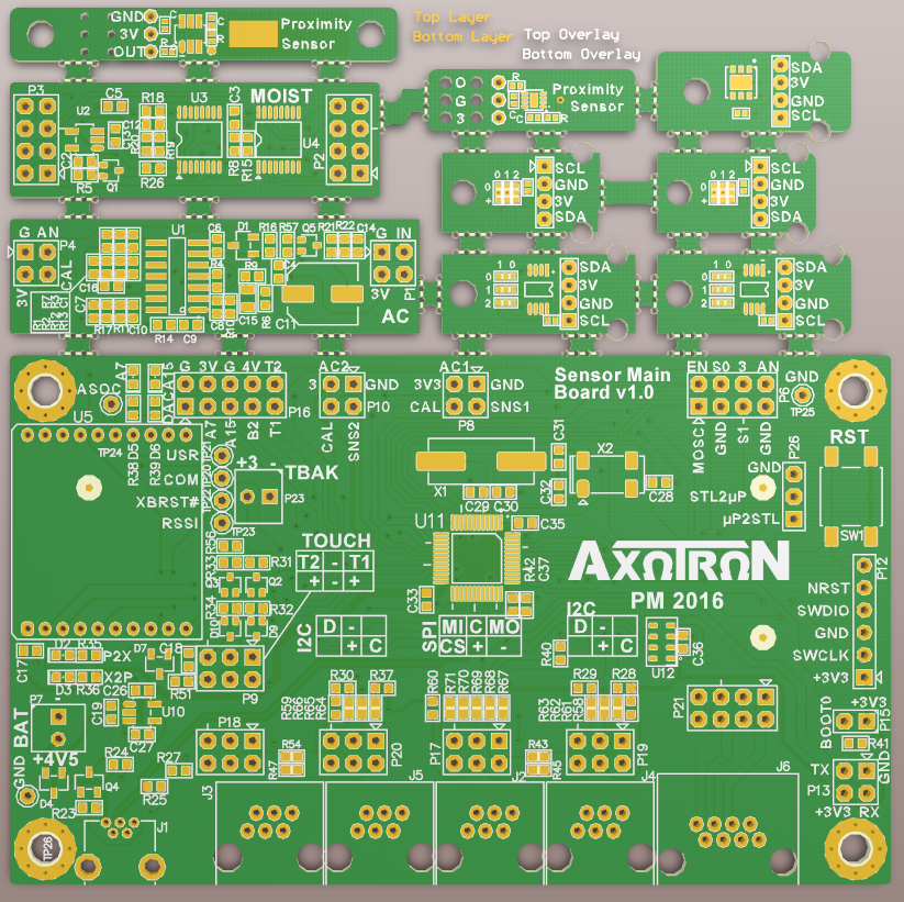
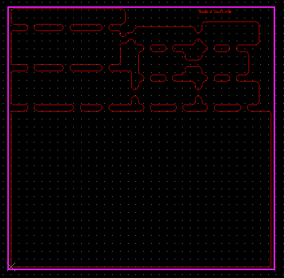
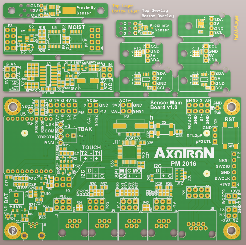
Today I finally sent a PCB I have been working on for a couple of weeks to manufacturing. It is a wireless sensor node based on a Cortex M0+ processor and an XBee ZigBee radio module. In addition to the main board with the processor and the radio, there are a couple of break-off sensor boards for measuring temperature, humidity, soil moisture, AC current etc. Here is a screenshot of the board:
More information will follow when I have assembled and programmed the board.
My orienteering club LOK (Linköpings orienteringsklubb) organized two events called Vårspringet during last weekend and I did among other things help with the online controls. In this blog post I describe the ROC, an online control solution based on a Raspberry Pi that we used for the first time.
Old online control solutions
For many years we have used two different kinds of online control solutions. The first one being concentrator boxes (“samlingsboxar”) with four serial port inputs where Sportident master units plug in. Our concentrator boxes have outputs that can drive at least 2 km of DL-1000 two-wire cable which brings the signals to the arena where they are received by special receiver boxes converting the signals back to proper RS232 serial port signals. This solution is obviously only applicable for online controls relatively close to the arena.
The other online control variant we have used are based on old Sony Ericsson mobile phones like M600i or P1i running custom programs (or apps if you will, but programs were not called apps when these were written by club members many years ago). In this solution, the SI master unit is connected to a serial-to-Bluetooth converter and the mobile phone receives the punch information via Bluetooth and sends it over GPRS to a server on the internet. The event administration program OLA polls the server and retrieves the punch information.
Trying something new – ROC
This year we planned on using a couple of the concentrator boxes, but also to retire the mobile phone solution and try out the Raspberry Pi based ROC “Radio Online Control” developed by Oskar and Erik Berg. This is a neat and pragmatic solution that makes use of several pieces of standard hardware and some not-so-standard software to create an online control that communicates via the 3G or 4G mobile phone network. Below is a photo of my setup where I put the hardware inside a metal cookie box dressed with some OSB board to keep things in place.
The hardware consists of a Raspberry Pi, a USB power bank, a USB-to-serial-port converter, an LED with series resistor, a piezoelectric buzzer, a 3G modem with SIM card, a Sportident master station and a number of USB cables. The ROC blog has recommendations on what and where to buy and how to connect things. In my case I had everything except the USB power bank and the 3G modem with SIM card. I borrowed the USB power bank from a club mate and bought a new 3G modem as described below.
The software is very kindly provided for free as an SD card image one writes to an SD card and inserts into the Raspberry Pi.
Getting it up and running
At first, one connects the ROC to an Ehternet network so that it can be registered on the roc.olresultat.se website. Configuration is done through the same ROC website and I would recommend a fairly detailed read of the ROC manual (only available in Swedish, use Google translate if you need) to figure out what should to be filled out and how. I failed to read the manual and ran into some trouble because of this later; see below.
A number of different 3G modems are supported as shown on the list on the right hand side of the ROC blog. I bought a Huawei E3351 modem in a package with a SIM card good for one month of data traffic through the operator “3” for 50 SEK at Kjell&Co. A pretty good deal I think.
At first I had trouble using the 3G modem and SIM card. The ROC did seem to connect to the server, but no punches got through and the connection seemed intermittent or flaky. I had the ROC connected to a monitor via an HDMI cable and got printouts every second that did not look right.
The ROC manual suggested that the problem might be that the Raspberry Pi could not supply enough current to the modem via its USB port, so I built a custom Y-shaped USB-cable that took current from the power bank while connecting the signals to the RPi. This did not help and I doubt it was necessary.
SIM card issues
I then tried the modem in a laptop and found an SMS on the SIM card that said that the month of data traffic on the SIM card was used up. Weird, since I bought it less than a day ago and the SIM card should be good for a month. I called the support at 3 and after 10 minutes of waiting for my turn, I talked to a support person who informed me that the SIM card had been used starting in October. Maybe someone at Kjell&Co had pulled the card out of its package and used it several months before it was sold to me? Or perhaps not since I think the PIN code was hidden under a scratch-off layer, so maybe it was 3 that had screwed up somehow? Anyway, the support guy seemed to believe my story and gave me a month of data traffic. After this, I still had some more issues and I suspected that my USB-to-serial converter with a Prolific chip was not supported.
The main problem however turned out to be that I had not read the manual carefully and therefore had failed to set up the APN (should be data.tre.se in my case) and PIN codes in the configuration form. Maybe I also had not configured the correct baud rate of the SI unit.
After some more trials and tribulations, I finally got the ROC to connect to the server via 3G, light up the LED, play a jingle on the buzzer and receive punches from the SI master station! Success!
I proceeded to install the hardware into the cookie box, but while doing so I seem to have zapped the IO pin on the RPi needed for the buzzer, so after this, only the LED indicates that it has managed to connect to the server and received the first punch. Fortunately this is good enough.
The web interface of the server roc.olresultat.se shows time-stamped connections and punches from the ROC. This is extremely helpful when troubleshooting or when verifying that the ROC is up and running. One thing I have learned from working with online controls over many years is that diagnostics and verification tools are enormously important (often sorely missing, though) when debugging the problems one encounter. There always seems to be something that does not work right from the start.
Bluetooth adapters
As an extra convenience, I decided to use two Bluetooth-to-serial adapters (previously used for the phone-based online controls) to eliminate the cable between the Sportident station and the ROC. After some digging, I found the CD with configuration software and was able to pair the two units such that they automatically established a serial link of the proper speed (4800 baud in this case) when powered up in range of each other. This link seemed to work reliably for the remainder of the “project”. The adapter on the control side was powered by an old headlamp battery via a cable with built-in voltage regulator I built many years ago for the phone-based online controls. To power the adapter on the ROC side, I soldered together another cable that took 5 V from the USB power bank and connected it to pin 9 of the 9-pin DSUB connector while routing the RS232-signals to the RS232-to-USB adapter. The bluetooth adapters and associated hardware is not shown in the photo at the beginning of the post since they had not been added when the photo was taken.
A couple of days before the first event, the guy responsible for the event administration software OLA set up OLA to receive punches from the ROC while I hooked up the ROC and punched a few times. This did at first not work, but it was quickly discovered that some setting in OLA was incorrect and after fixing that, everything seemed to work fine.
All of the above took maybe two weeks or so of calendar time, so it was good that I started working on the ROC a couple of weeks before the events.
Success, failure and success during the events
During the Saturday event, the ROC worked brilliantly and without any hitches.
During the Sunday event however we experienced some issues that are hard to understand. When I first started the ROC on Sunday morning, it quickly connected to the 3G network and received punches. Perfect, just like the day before.
But then we decided to set up a new event ID in the ROC configuration interface instead of continuing on the Saturday event ID. (This was most certainly not necessary.) After doing so and restarting the ROC, it did not react to punches, even though the connection to the 3G network was fine. More restarts did not help and neither did bypassing the Bluetooth adapters.
We then went back to the previous event ID in the configuration interface and after a few restarts the ROC started relaying punches again. Phew. Now we were in a hurry to get the ROC out in the woods to the control where it should do its task. Just like the previous day, we let it stay powered on to make things easy for the people installing it in the woods. When they were done, it did unfortunately refuse to relay punches once again, even though it was solidly connected to 3G.
As a final try to get it working, we sent out another guy to replace the SI station in case it had a broken cable or something. This did not help and the guy had to stay in the woods and report in passing competitors manually via SMS. After maybe 15 minutes something odd happened however. Punches started to stream in from the ROC! This continued to work for the rest of the event.
I still have no idea why the ROC worked intermittently during the Sunday event. It looked so good on Saturday and during the limited tests in the week before the events.
Conclusions
I think the ROC is a pretty neat online control solution, not the least because it is so inexpensive. In my case I spent only 50 SEK since I had the rest of the required hardware already. Pretty hard to beat. The time I had to invest was perhaps not quite as short as I would have liked, but this was partly due to my failure to read documentation and partly due to problems with the SIM card caused by the 3G operator or some other external party. Next time I am sure it will be much quicker.
There are some details that could perhaps be better documented and easier to troubleshoot, but for the cost of free it is hard to complain about the software. The instabilities we experienced during Sunday is a bit troubling and I would like to understand what the problem was.
We will most likely use at least one ROC on our events next year.
Hints
Here is a random list of things that might not be too clear from reading the manual:
If you want to log into the Raspberry Pi via SSH while it runs the ROC software, you can use the user name “pi” and the password you set in the web configuration interface.
It is unclear what serial port adapters are supported, but I would guess that most are supported since I could find no complaints or questions regarding this on the ROC blog.
Directly connecting Sportident USB masters to the RPi is also supported, although I have not tried this myself.
There are other networking options than using 3G in the case where the ROC is in WiFi- or Ethernet range of the finish. See the manual for details.
Designing passive LC-filters typically involves looking up prototype filter component values in a table in reference books like “Handbook of Filter Synthesis” by Zverev or “Design of Microwave Filters, Impedance-Matching Networks, and Coupling Structures” by Matthaei et. al., then transforming the values to produce a filter with the desired impedance and cut-off frequency. This can be a bit tedious and error prone, so when I found out about the classic Matthaei book, which is downloadable via the link above, and that it contains the math required to calculate the prototype filter component value tables, I set out to create a spreadsheet to help with the filter design.
In addition to calculating the (previously) magical prototype tables for Butterworth and Chebyshev (with user-specified pass-band ripple) filters, the spreadsheet also performs the frequency and impedance transformation for filters of orders from 1 to 10.
To make the design process even quicker and better, I added a feature to create LTSpice schematics of the selected filter so that the filter properties can be simulated (and perhaps manually adapted to standard component values and to include parasitics) using LTSpice. I used the SI prefix formatting function I wrote about in the previous blog post to write out the component values in a pretty manner.
The usage of the spreadsheet should be fairly self-explanatory, but there are also usage instructions on the first tab. Basically, the user should fill out the values in yellow cells and leave the rest alone. I did not lock any cells, since I often get annoyed by spreadsheets with locked cells and I encourage others to modify and improve it.