I am taking care of a number of Sportident units, which are used in the sport of orienteering. These are small embedded systems powered by non-rechargeable lithium batteries, specifically thionyl chloride (Li-SOCl2) batteries, and every few years the batteries need to be replaced, depending on how much the unit has been used. The units themselves tries to keep track of the battery status by dead reckoning and by measuring the battery voltage, apparently while it is doing something that consumes current. The state of the battery voltage under load can be read out as can the value of the estimated remaining capacity.
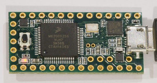
To help in determining the status of such batteries, I wanted to have a device that could measure the voltage and the internal resistance in a convenient manner. I had a Teensy laying around and since it has a DAC output and several analog inputs, it looked like a good platform to quickly hook something together that could do the task.
This is the schematics I came up with:
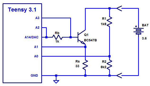
The circuit works like this:
R1 and R2 forms a voltage divider that reduces the battery voltage to below 3.3 V which is the limit of the ADC of the Teensy. Q1 and Rs forms a current sink controlled by the voltage on the A14/DAC pin. Basically the DAC pin sets the base voltage and since the base-emitter voltage is fairly constant, a constant voltage will develop over the emitter resistor Rs. To maintain this voltage Q1 will conduct as much current as required from the battery. The emitter current can be measured by measuring the voltage drop across Rs using analog input A1.
The purpose of having A2 and A3 connected across the base resistor is to be able to measure the (small) base current so that it can be subtracted from the emitter current when calculating the battery current. This is only a small correction and not really important, but since the inputs were available and it was easy to do, I added this little feature.
I built the physical circuit on perfboard and it looks like this:
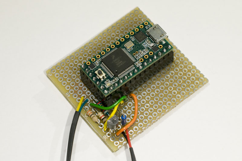
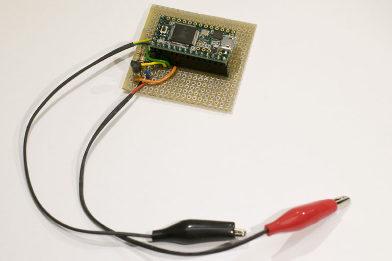
As can be seen, the whole thing is very simple to build as the Teensy does all the heavy lifting.
I did of course need a program to control the whole thing and do all the measuring, calculations and presentation of results. This is the program I came up with:
/* Lithium battery tester

   Tests the internal resistance of a small 3.6 V lithium battery by ramping up the load current and measuring
   the pole voltage and calculating the internal resistance.

   Written by Per Magnusson, http://www.axotron.se
   v 0.1 2015-05-24
   This program is public domain.
*/

const float Rtop = 1817;       // Top resistor of divider, ohms
const float Rbot = 8170;       // Bottom resistor of divider, ohms
const float Rs = 32.8;         // Current sense resistor, ohms
const float Rb = 995;          // Base resistor, ohms
const float Vref = 3.3;        // ADC reference voltage, volts
const int ADCbits = 12;
const int DACbits = 12;
const float voltPerADC = Vref/((1<<ADCbits) - 1.0); // Factor to convert ADC codes to volts
const float voltPerDAC = Vref/((1<<DACbits) - 1.0); // Factor to convert DAC codes to volts
const float DACperVolt = 1/voltPerDAC;              // Factor to convert volts to DAC codes
const int detectLimit = 0.8/voltPerADC;             // Limit for detecting battery
const float curLim = 35.0e-3;  // Maximum test current in A
const float curStep = 5.0e-3;  // Target current step
const int maxIter = 3;         // Number of iterations to reach target current

const int vsensePin = A0;      // Voltage sense pin
const int curSensePin = A1;    // Emitter current sense pin
const int baseSenseHiPin = A2; // High base current sense pin
const int baseSenseLoPin = A3; // Low base current sense pin
const int dacPin = A14;        // Current control pin
const int ledPin = 13;         // LED for debug

const byte sWaitNoBat = 0;
const byte sWaitBat = 1;

byte state;

void setup() {
  Serial.begin(57600);
  analogWriteResolution(DACbits);
  analogReadResolution(ADCbits);
  analogWrite(dacPin, 0);
  pinMode(ledPin, OUTPUT);
  state = sWaitNoBat;
  Serial.println("Battery tester");
  digitalWrite(ledPin, HIGH);     // turn  LED on
  delay(3000);
  digitalWrite(ledPin, LOW);     // turn  LED off
  Serial.println("Waiting for a battery to be connected...");
}

void loop() {
  int voltCode;
  int baseVoltCode;
  int curCode;
  int dacVal;
  int dacStep;
  float volt;
  float voltNoLoad;
  float curNoLoad;
  float cur;
  float baseCur;
  float res;
  float prevCur;
  float targCur;
  float stepCur;
  byte testBat;
  byte iter;

  analogWrite(dacPin, 0);  // Make sure we are not loading the battery in this state
  testBat = false;
  voltCode = analogRead(vsensePin);  // Read battery voltage to see if it is connected
  if(state == sWaitNoBat) {
    // We are waiting for at battery to be connected
    if(voltCode > detectLimit) {
      // A battery was connected
      testBat = true; // Proceed to test it
    }
  } else if(state == sWaitBat) {
    // We are waiting for a battery to be disconnected
    if(voltCode < detectLimit) {
      // A battery was disconnected
      Serial.println("\nWaiting for a battery to be connected...");
      delay(1000); // Delay to not react on glitches while the battery is being disconnected
      state = sWaitNoBat;
    }
  }

  if(!testBat) {
    // Not in a situation that a battery should be tested
    return;
  }

  // Test the battery
  Serial.println("Battery connected, waiting for connection to stabilize.");
  delay(1000); // Wait for the connection to stabilize
  voltCode = analogRead(vsensePin);
  if(voltCode < detectLimit) {
    // The battery is gone, it was just a glitch
    state = sWaitNoBat;
    Serial.println("Battery removed, aborting.");
    Serial.println("Waiting for a battery to be connected...");
    return;
  }
  digitalWrite(ledPin, HIGH);     // turn  LED on
  Serial.println("Testing battery.");

  voltNoLoad = voltCode * voltPerADC * (Rtop+Rbot)/Rbot;
  volt = voltNoLoad;
  curNoLoad = voltNoLoad/(Rtop+Rbot); // "No load" current

  Serial.println("");
  Serial.print("Unloaded voltage: ");
  Serial.print(voltNoLoad);
  Serial.print(" V (current = ");
  Serial.print(curNoLoad*1000);
  Serial.println(" mA)");

  // Ramp up the current
  cur = 0;
  targCur = 0;
  dacVal = 0.66*DACperVolt;       // Base drive starting value, 0.66 V, low current
  dacStep = 5.0e-3*Rs*DACperVolt; // Increment ~5 mA per iteration
  prevCur = 0;
  iter = maxIter;                 // First step is to read whatever current the starting DAC value results in

  // Loop to set a number of different battery test load currents and measure the battery performance at each current
  while(1) {
    if(targCur > curLim) {
        // We are beyond the maximum target current, normal exit from loop
        break;
    }
    if(dacVal >= (1<<DACbits)) {
      // The DAC value is too big, exit from loop
      Serial.print("Warning: Above maximum DAC setting (");
      Serial.print(dacVal);
      Serial.println("), exiting");
      break;
    }

    analogWrite(dacPin, dacVal);                      // Drive the base of the transistor
    delay(10);
    voltCode = analogRead(vsensePin);                 // Battery voltage reading
    volt = voltCode * voltPerADC * (Rtop+Rbot)/Rbot;  // Calculate battery voltage
    baseVoltCode = analogRead(baseSenseHiPin) - analogRead(baseSenseLoPin); // Read voltage drop across base resistor
    baseCur = baseVoltCode * voltPerADC/Rb;           // Calculate base current
    curCode = analogRead(curSensePin);                // Emitter current reading
    // Calculate battery current and compensate for base current and divider current
    cur = curCode * voltPerADC/Rs - baseCur + curNoLoad;

    if(voltCode < detectLimit) {
      // The voltage is too big, exit from loop
      Serial.print("Warning: Below minimum battery voltage (");
      Serial.print(volt);
      Serial.println(" V), exiting");
      break;
    }

    if((cur - curNoLoad) > 0) {
      res = (voltNoLoad - volt)/(cur - curNoLoad); // Calculate internal resistance
    } else {
      res = 0; // Avoid dividing by zero
    }
    if(iter < maxIter) {
      // Make a small adjustment to get closer to the target current
      if(cur != prevCur) {
        dacVal += dacStep*((targCur-cur)/(cur-prevCur));
      }
      iter += 1;
    } else {
      // Print result
      Serial.print("Voltage: ");
      Serial.print(volt);
      Serial.print(" V");
      Serial.print(" Current: ");
      Serial.print(cur*1000);
      Serial.print(" mA");
      Serial.print(" Resistance: ");
      Serial.print(res);
      Serial.println(" ohms");

      // Move to next target current
      targCur += curStep;
      if(prevCur > 0 && (cur-prevCur > 0)) {
        // Estimate the step size required to reach the next target current
        dacStep = dacStep*((targCur-cur)/(cur-prevCur));
      }
      dacVal += dacStep;
      prevCur = cur;
      iter = 0;
    }
    if(cur > curLim*1.2) {
      // The current is too big, exit from loop
      Serial.print("Warning: Maximum current exceeded (");
      Serial.print(cur);
      Serial.println(" mA), exiting");
      break;
    }
  }
  analogWrite(dacPin, 0);        // Stop the battery current drain
  digitalWrite(ledPin, LOW);     // turn  LED off
  state = sWaitBat;
  Serial.println("Done");
  Serial.println("Disconnect battery.");
}
The program sends information to a serial terminal (I used the one inside the Arduino development environment). It waits for a battery to be connected and then ramps up the current and reports the pole voltage as well as the internal resistance at a couple of different load currents. This is what the output can look like:
Waiting for a battery to be connected...
Battery connected, waiting for connection to stabilize.
Testing battery.

Unloaded voltage: 3.67 V (current = 0.37 mA)
Voltage: 3.63 V Current: 1.39 mA Resistance: 39.36 ohms
Voltage: 3.47 V Current: 4.97 mA Resistance: 41.95 ohms
Voltage: 3.27 V Current: 9.99 mA Resistance: 41.26 ohms
Voltage: 3.08 V Current: 15.03 mA Resistance: 40.23 ohms
Voltage: 2.89 V Current: 19.98 mA Resistance: 39.33 ohms
Voltage: 2.72 V Current: 24.97 mA Resistance: 38.56 ohms
Voltage: 2.54 V Current: 29.99 mA Resistance: 37.88 ohms
Voltage: 2.37 V Current: 34.99 mA Resistance: 37.33 ohms
Done
Disconnect battery.
With a different program, the circuitry can of course also be used to test batteries in different ways.
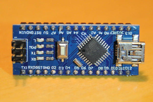
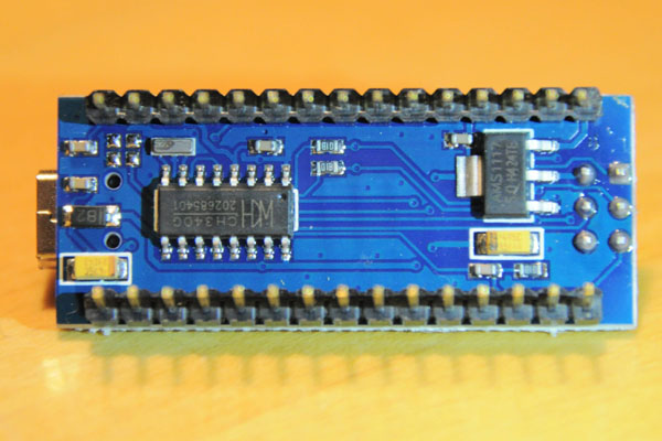
Update on 2015-10-11
As requested by Alex in the comments, here is a picture of the bottom side of the board (and the corresponding picture of the top).