Category Archives: Arduino

Review of New Arduino Nano from Banggood

As I wrote in a previous blog post, I had a bad experience when ordering some Arduino Nanos (SKU066316) from Banggood.com. The products turned out not to be working due to faulty and possibly counterfeit FT232RL chips (USB to serial port converters).

“Thea” from Banggood commented on the post and as a result of my criticism, Banggood claims to have changed their supplier. Almost a month ago Thea offered to send me one of their new Nanos for me to review and today I received it. The parcel was stamped 2013.12.12.20 (not sure what the trailing “.20” means) which probably indicates it was sent on the 12th of December, just after Banggood said they were about to ship it. So the delay is probably just the time it took for the mail to get here.

This blog post is a review of what I received. A short summary is that the board I received performs slightly better than the old boards, but that there still seems to be major problems and possibly still a counterfeit FT232RL chip that is at the root of the problems.

Appearance

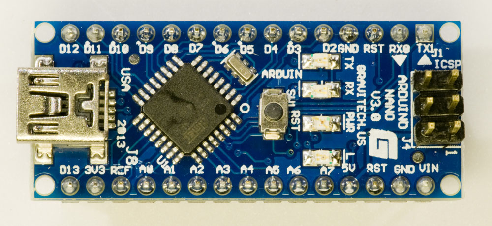
The new Arduino Nano I got looks a little different from the old ones. It has the following text printed on it:

ARDUINO
  NANO
  V3.0
GRAVITECH.US
ARDUIN
USA 2013

This is what it looks like:

Top side of Arduino Nano
Top side of Arduino Nano, claiming that it is made by Gravitech
Bottom side of Arduino Nano

Gravitech is the company that designed and originally built the Nano. Since long ago, I have a Nano made by them (probably bought through Digikey) and on it is printed V3.1 and “USA 2011”. It seems a bit odd that they would be making V3.0 in 2013 when they were already making V3.1 in 2011, but I guess that it is possible that they maintain two versions for some reason.

Power LED color

On Gravitechs web site, they say that the Nano V3.0 has a blue power LED. This is true for the old Arduino Nano that I have, but not for the new one I received from Banggood. Below are photos of both the new and old board when powered up, showing the green LED on the board from Banggood and the blue LED on the old board.

Green power LED
Top side of Arduino Nano from Banggood with green power LED.
Blue power LED
Top side of old Arduino Nano bought on Digikey with blue power LED.

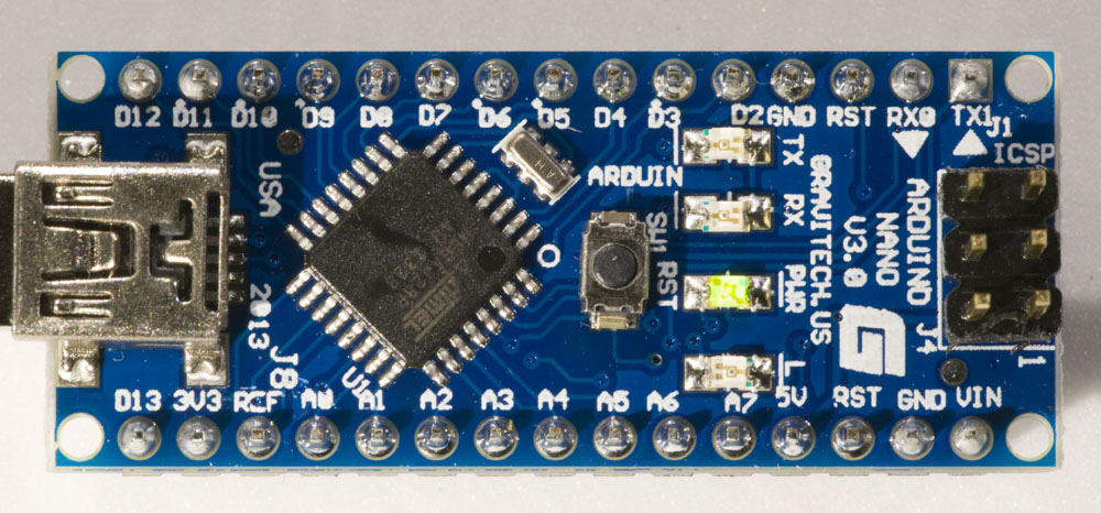
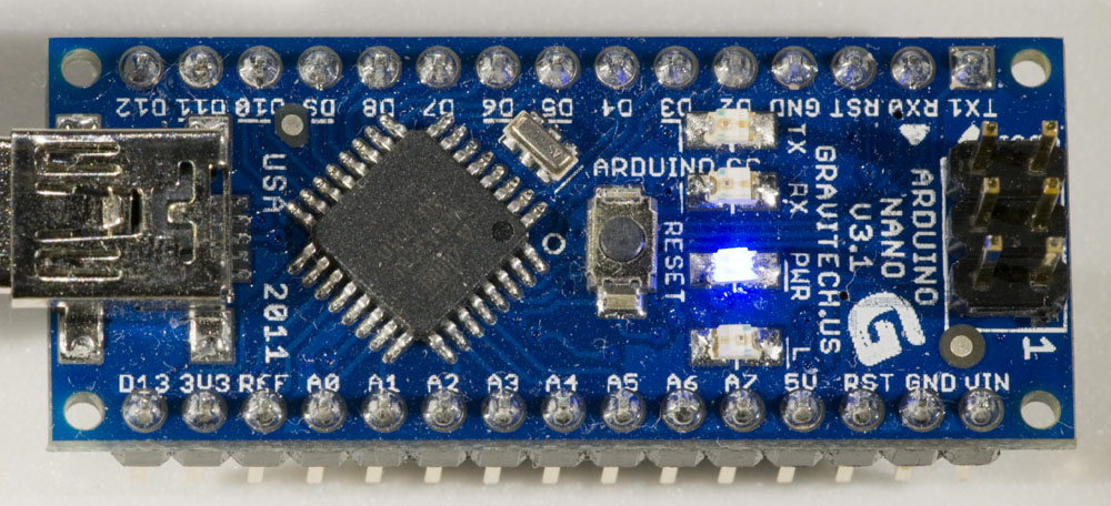
Well, the power LED being green instead of blue is not a problem for me. The fact that the text says “ARDUIN” on the Banggood board and “ARDUINO.CC” on the Digikey board is curious. Is it likely that Gravitech has introduced that error after getting it right a few years ago? A picture at the bottom of the Gravitech page for Arduino Nano does show correct silkscreen print on a V3.0 board from 2009…

Problems when connecting the Arduino to the computer

I connected the board to my computer (running Windows 7, 64-bit) via a USB cable. At first it did not appear as a USB serial port, but unplugging and reconnecting it made it show up as COM16. I tried to upload a sketch to it and that worked. So far so good.

Then the problems began. I tested to unplug and reconnect the board several times and it turns out that it very often does not work as it should. A few different things happened at different times:

  • The USB serial port shows up as it should in the Device Manager.
  • An unrecognized USB device shows up in the Device Manager.
  • A pop-up message says the device failed to start.
  • The device is completely unrecognized.
  • The computer crashes with a blue screen of death (BSOD).

Here is an account of a series of tries:

  1. Not recognized.
  2. Works fine.
  3. Not recognized.
  4. Computer crash (BSOD).
  5. Works fine, but with a new COM port number (I think it should always be the same).
  6. Works fine.
  7. Not recognized.
  8. BSOD
  9. Works fine.
  10. Not recognized.
  11. Cannot start.
  12. Not working, but shows up with a yellow question mark in Device Manager. Inactivating and then activating it got it working.
  13. As above, but inactivating and then activating did not help.
  14. Unknown device.
  15. Unknown device.
  16. Unknown device.
  17. USB serial converter could not start. Inactivating and then activating did not help.

Not exactly a stellar performance and clearly unacceptable, especially the BSODs.

As a reference I tried to plug and unplug both the old V3.1 Nano from Gravitech/Digikey and one of the Nanos I previously bought from Banggood and on which I replaced the FT232RL chip to get them working. Both of these units worked fine every time for at least 10 tries. The only exception is that a few times the computer did not recognize the unplugging of the Nano. I think that happened when the unplugging occurred rather quickly after plugging it in. But there were no problems with unrecognized devices or computer crashes.

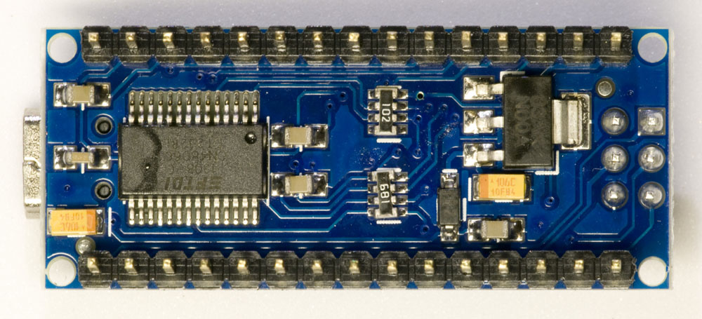
The FT232RL chip on the new Nano from Banggood has text that is laser marked (not printed) like the previous Nanos I have received from Bangood, but unlike all the other (working) FT232RL chips I have seen.

FT232RL
Close-up of the FT232RL USB to serial converter on the new Nano from Banggood.

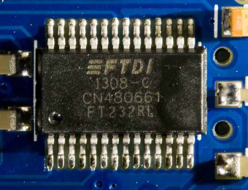
So in while it was great of Banggood to send me a new unit to try, there still seems to be major problems with the Arduino Nanos from Banggood and my guess is that the FT232RL USB to serial converter is still the main problem. Perhaps it is (still?) counterfeit. It would be interesting to use a USB analyzer to compare the traffic between the (old) working units I have got and the intermittent one I reviewed here, but I currently do not have access to such a tool.

I also doubt that these Nanos are genuinely from Gravitech. The price seems way too low compared to what they are selling them for on their own web site, and the color of the power LED as well as the appearance of the silkscreen print on the board (missing letters, V3.0 still produced in 2013) casts doubts on the origin.

More time-lapse photography

I wanted to make more time-lapse videos of the magnetic putty doing other tricks. For this I decided to also add some new features to the time-lapse controller, namely the ability to dynamically increase and decrease the rate at which the pictures were taken.

The reason I wanted this functionality is that sometimes things happen more quickly and sometimes more slowly, so being able to adjust the shutter rate seemed like it would allow more interesting videos to be created. It was not particularly difficult to implement this and the resulting code can be found here:

Version 0.2 of the Arduino time-lapse controller sketch.

With these new features I am firmly beyond the abilities of the built in time-lapse function of the D300 camera, so now there is at last a good motive to build an external time-lapse controller (in addition to the fun of it).

I made use of the new functionality while recording three new videos of strands of magnetic putty being pulled up towards a magnet. The result can be seen below.

I still am not sure what causes the flickering in the videos as I supply the LED light from a lab power supply set up to function as a constant current source. The only other light source in the room is my computer monitor which is aimed away from the scene.

Time-lapse shutter release based on Arduino

Combining electronics and photography can be quite fun. Here is a description of a mini-project I did recently.

I have some magnetic putty that I wanted to take time lapse video of. I also have a digital still camera (Nikon D300) and a manual remote shutter release with 2.5 mm stereo jack connectors. There are remote shutter releases with time-lapse functionality built in, but this was not present on mine, so instead I decided to create the time-lapse functionality by means of an Arduino Nano. (After almost completing this post, I realized that there is in fact a shutter release timer feature in the D300 menus. Duh! So I could have used that if I had settled for having the same time between each pair of exposures.)

Interfacing to the camera is quite simple. Two open collector outputs are needed, one for pressing the shutter release button halfway (to focus) and one for pressing it all the way down to take the picture. Some experimentation showed that it is necessary to first emulate pressing the button halfway and then release the shutter. It did not work if the halfway step was skipped.

It would probably be possible to use Arduino pins directly to talk to the camera by switching the pins between tri-state (button not pressed) and low (button pressed), but I decided to use external transistors to ground the signals instead as shown in the schematic below.

Shutter release schematic
Circuit for interfacing an Arduino to the shutter release cable.

The signals Release and Focus go to Arduino pins.

In addition to the camera control signals, I added a power MOSFET connected to another Arduino pin in order to control LED lighting. This might be useful when the period between pictures is very long to save power and prevent the LED from getting unnecessarily hot. In the end I did not use this feature as I suspect it might contribute to somewhat varying light intensity between shots which would appear as flicker in the resulting video.

The hardware based on an Arduino Nano. Remote shutter release cable goes out to the right. Shown are also cables and a big capacitor for controlling an LED lamp and some unrelated circuitry.
The hardware based on an Arduino Nano. The remote shutter release cable goes out to the right. Shown are also cables and a big capacitor for controlling an LED lamp, the USB cable and some unrelated circuitry.

Some code is of course also necessary. I decided to control the operation via the USB cable using the serial monitor. Since the process I intended to film tended to have the most action at the beginning, I made the intervals between the exposures longer and longer. This kind of feature is perhaps not so easy to get from a commercial remote release timer.

The code is available here.

The functionality is very rudimentary and the code should be pretty self explanatory with the few comments that are included.

Capturing the series of photos

So, now we have the hardware and software to capture the time lapse photos. What is next is to set up a little photo studio where the action can take place and configure the camera. There are a number of things to consider in this process. Here are some that I figured out:

  1. Make sure you have a freshly charged battery in the camera and enough space on the memory card.
  2. Even HD videos have much lower resolution than still images from DSLRs. To limit the amount of data you will have to deal with, set the resolution to the smallest value bigger than the resolution you want your film to be. Also, it is probably good enough to select the lowest JPEG quality that the camera supports to further minimize the size of the image files. The video compression is anyway likely to be the limiting factor rather than the quality of the JPEGs.
  3. Lighting is important. I used a single LED desktop lamp, but I replaced its power supply by a bench supply to make sure there was no flicker from the mains. Light sources that flicker with the mains frequency are actually probably OK to use provided the exposure time is an integer multiple of the half period of the mains. In Europe the mains period is 50 Hz, so the half period is 1/100 s. This means that exposure times like 1/100, 1/50, 1/25, 1/10 etc are OK, but not e.g. 1/60 or 1/200.
  4. To further prevent the light from flickering in the video, it is pretty important to shield off any uncontrolled or variable light sources, like light from a window, a computer screen, lamps that might be occluded by you walking by etc. The ideal case is probably to have the setup in a windowless room where the only light sources are the ones you intentionally use to illuminate the subject.
  5. Since you will probably be shooting in JPEG (not raw), it is important to set the white balance correctly. Do not set it to auto.
  6. Put the camera on a tripod.
  7. Compose the scene such that your subject will stay inside it during the action. Consider that you might want to crop the pictures to 16:9 which is a common video aspect ratio. This means that you will lose some of the top and/or bottom of the field of view.
  8. Use auto focus to get the focus right, but then switch over to manual focus. You do not want the camera to try to refocus for every exposure.
  9. You probably want a small aperture, perhaps between f/10 and f/22 to get a large depth of field since the subject might move away from or towards the camera during the filming and you do not want it to get out of focus.
  10. Set the camera on manual to peg both aperture and exposure time so that they do not change between shots. That would otherwise result in flicker in the video.
  11. Take a picture manually to see that it looks fine in terms of exposure, composition, white balance and focus.
  12. Perhaps you want to turn off preview on the camera display to save battery. On the other hand it might be useful to be able to preview what the camera sees during the shoot.

Below is a photo of my make-shift setup under a desk.

"Photo studio" setup
“Photo studio” setup

When all is set up properly, it is time to start the interval timer by giving the proper command in the serial monitor and then just wait until all the action has been captured.

I will describe how to make a video based on all the JPEGs in the next post.