We are about to move to a house where most of the floors are making creaking noises when you walk over them. The floors are made of 22 mm thick wooden boards and below them there is an underfloor hydronic heating system with hot water pipes embedded in heat spreading sheets of aluminum as shown below.
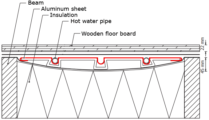
One of the possible solutions to the creaking floor problem is to use screws to tie down the boards into the underlying wooden beams. There are few problems however. One is to locate the beams, but a more important issue is to make sure that we do not drill or screw into one of the water pipes. Doing so would obviously have catastrophic consequences. So how can one be sure to stay clear of the water pipes? We will borrow an IR camera and try to see how the pipes are routed, but I am not so sure this will clearly show all the pipes everywhere since the pipes might not be in good contact with the floor boards everywhere.
Another idea is to take advantage of the heat spreading sheets of aluminum placed between the beams. The pipes are sure to be straight and positioned a safe distance away from the beams everywhere where aluminum sheets are present. Close to the walls however the sheet metal will end to give the pipes space to curve around to reach the next pocket between the beams. It seems quite important to detect where the aluminum ends close to the walls so that we know where the danger zone is. Below is an example sketch of what the pipe layout might look like in a few rooms.

Hidden metal can be detected by a metal detector, but I do not have one of those. Buying one is obviously an alternative, but would it perhaps be possible to build one without too much effort?
I pondered this for a day or two. One principle to use would be to measure the inductance and/or loss of a coil. Probably there should be a noticeable change when metal interferes with the magnetic field. Another method would be to sense the coupling between two coils, which should also be affected by nearby metal. But could I quickly and easily build a circuit to do this? After all, a commercial metal detector might not be all that expensive.
A relatively simple and common way of detecting a change in inductance would be to build an oscillator where the coil forms part of the tank circuit of the oscillator and then detecting the frequency change somehow. This is certainly doable, but I came up with another idea that seemed quicker to implement with available hardware, namely to use my little vector network analyzer, the VNWA!
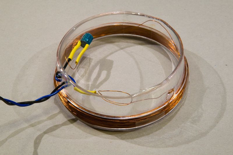
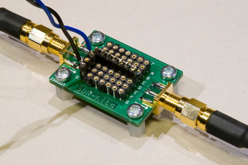
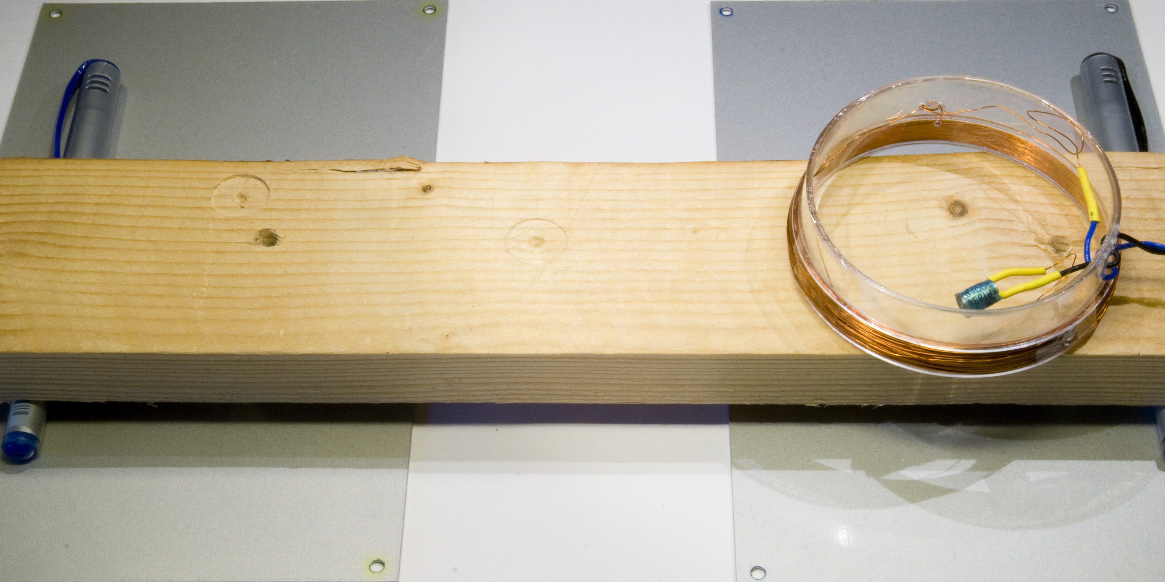
So I wound a wide and flat coil using two cut-off disposable plastic cups as the coil former. Then I put a 390 pF capacitor in series with the coil and placed the series LC-circuit as a shunt across the VNWA test board connected for a through (S21) measurement. Pictures of the coil and the connection to the test board are shown below.
Thus, at the frequency where the LC-tank is resonant, it will be quite successful at shunting the transmission line and thus reducing how much signal power gets through to the receiving port of the VNWA. I.e. the transmission parameter S21 will have a notch at the resonant frequency. When the coil comes close to metal, one can expect the inductance as well as the loss to change. A change in inductance will lead to a change in notch frequency while increased loss will show up as a less deep notch.
I did not know what parameter of the coil would be most sensitive to nearby metal, but using the VNWA it is easy to observe several parameters at once over a range of frequencies. I also did not know precisely at what frequency the tank circuit would be resonant, but it is very easy to find out using the VNWA. Another thing that is convenient with the setup is that performing a thru calibration does not require any tedious SMA connector screwing/unscrewing. Just unplug the cable to the sense coil and do the calibration. This is particularly nice when iteratively optimizing sweep parameters like start and stop frequencies, number of frequency points per sweep and dwell time at each frequency.
So did it work?
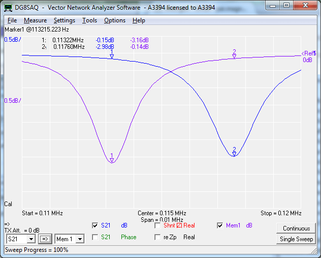
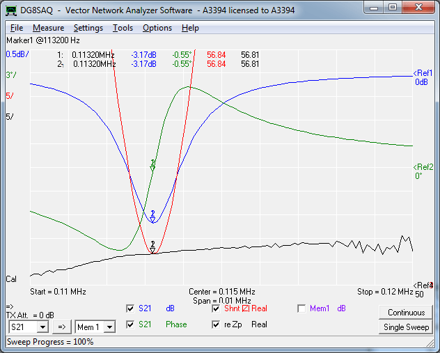
The resonance frequency without nearby metal turned out to be about 113 kHz, so since the capacitance is 390 pF, the inductance is apparently 5.1 mH. When the coil is 30 mm above a sheet of aluminum, the frequency changes to 115 kHz. If it is just 20 mm above aluminum, the frequency goes up further to 117.5 kHz. The notch in S21 is about 3 dB deep and 2 kHz wide, so it is very easy to detect the change in notch frequency. Below is a plot showing S21 when the coil is 30 mm above a 50 mm wide gap in the aluminum sheets (Mem1 with a notch frequency of 113.2 kHz) and another trace showing S21 when the coil is 30 mm above an aluminum sheet (S21 with a notch at 115.3 kHz).

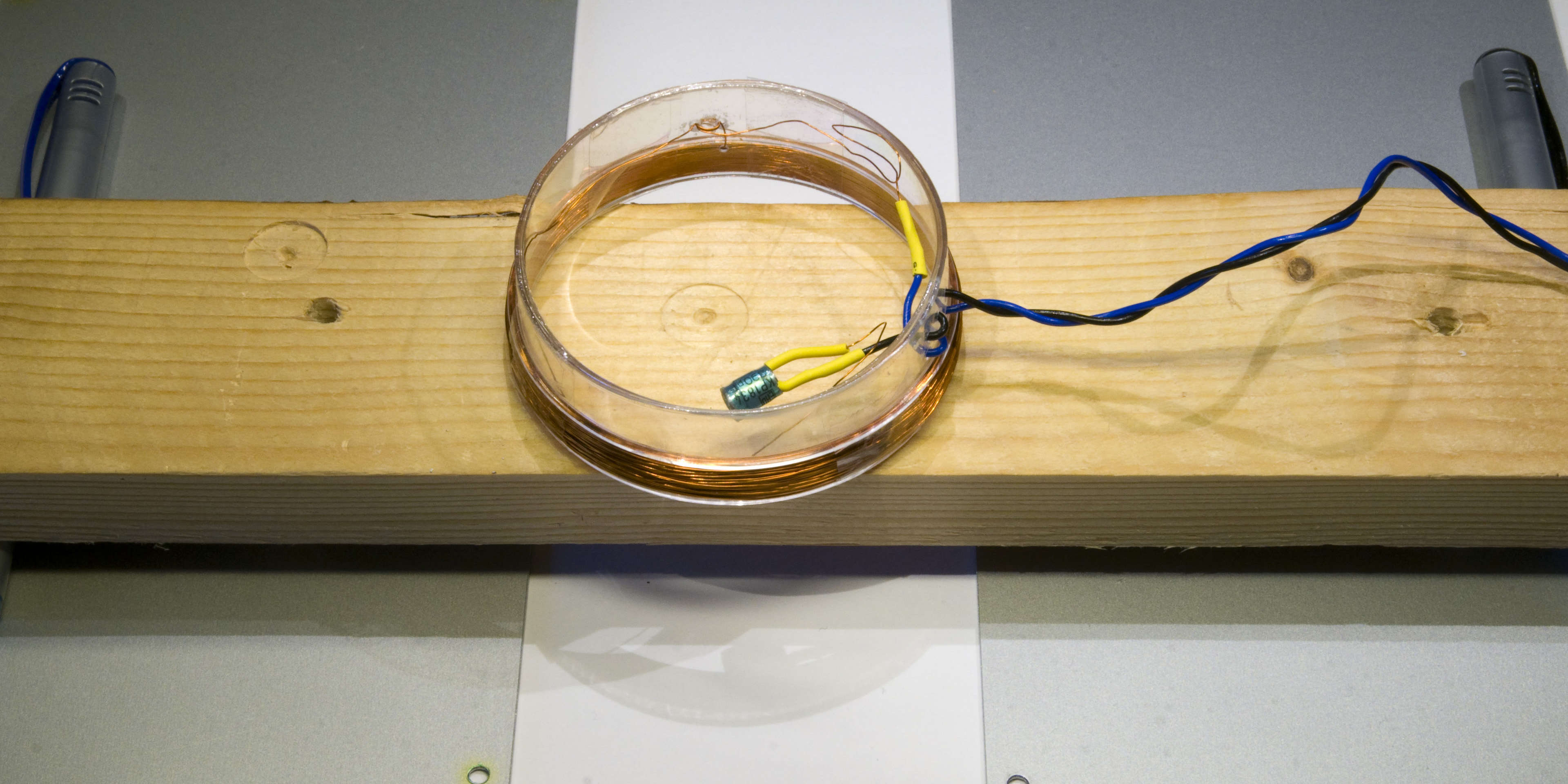
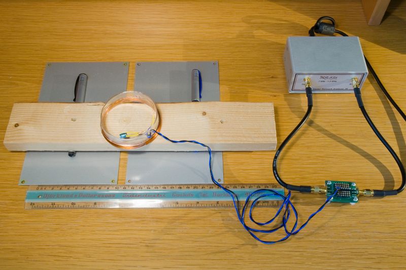
Below are some pictures of the test setup.
It turns out that the amount of frequency change (inductance change) is strongly dependent on the distance to the metal. If the distance is decreased to 20 mm, the frequency goes up to 117.6 kHz when over the metal, while it is almost unaffected when over the gap.
If the distance is increased to 46 mm, the frequency change is small, but still very much detectable, from 113.0 kHz to 113.8 kHz.
How small gaps can be detected?
I expect there to be about 10 cm or so of gap between the metal sheets, but it can be interesting to know if the setup also can detect much smaller gaps. So I tested this and found that a 10 mm gap at 30 mm distance from the coil results in a frequency of 114.1 kHz, which is well separated from the 115.3 kHz we see when the coil is directly over the metal. So even this small gap is easy to detect.
Since the notch is relatively strong and easy to detect using the VNWA, the sweep time can be short, which is good when quick feedback is desired while moving the detector coil across the floor. For all measurements shown above, I used a sweep of 101 points with a dwell time on each point of 3.33 ms, resulting in a sweep time of 0.34 s.
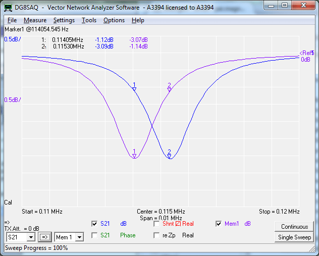
I wrote earlier about the different coil parameters that would potentially change with nearby metal. In the end it turned out that the frequency of the notch in S21 of the shunting tank circuit was the most convenient parameter to use, which means that it is the change in inductance of the coil that is primarily detected. I tried a couple of other parameters as well using the math capability of the VNWA, but nothing worked better than the S21 notch frequency. Below are plots of S21, the phase of S21, the magnitude of the shunting impedance and the real part of the shunting impedance for the cases where the coil is over a 50 mm slot and when it is directly over the metal.
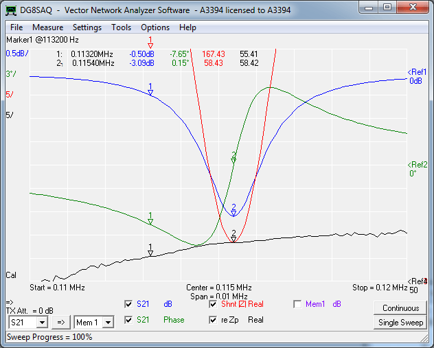
As can be seen, the shunting impedance has a notch that is also easy to detect and the phase of S21 has a distinct transition at the notch. The location of all of these features along the frequency axis are directly determined by the coil inductance.
The real part of the shunting impedance (the ESR of the coil, the black curve above) is not affected very much at all and seems to be pretty useless in the detection of metal.
Some false starts and optimizations
It took an hour or two to build the first incarnation of this metal detector, but it was not quite as good as the version I have described above. Without thinking much I wound the first coil on a 50 mm diameter cardboard tube without taking any measures to make sure the winding was as close as possible to the end of the tube. Then I put a 1.5 nF capacitor in parallel across it and connected it as a shunt to the test board. Several things were suboptimal in this configuration.
Problem number 1: Using a parallel tank circuit means that the impedance is at maximum at the resonant frequency. This further means that the least amount of attenuation in S21 will occur at the resonant frequency, so S21 should have a peak here. However, with the component values selected, the attenuation around the peak will be pretty minimal and so the peak will be very small. Calculating the shunting impedance from S21 brings out the peak more clearly. This worked, but the peak was very noisy and I had to use a relatively slow sweep to detect it clearly. It would have been better to put the parallel tank in series with the VNWA signal instead of shunting it as a peak in impedance would then have resulted in a significant notch in S21 that would have been easier to see. The other option is to use a series LC tank and let that shunt the signal, which is obviously the solution I later selected.
Problem number 2: Reducing the distance between the coil and the metal strongly increases the sensitivity. So it is a good idea to try to keep the coil as close to the floor as possible. Having the coil spread out over maybe 15 mm of tube and with a distance of 5 mm from the end of the tube to the nearest coil windings is rather wasteful. A better coil design would have increased the sensitivity and this was addressed in the second design.
Problem number 3: A larger diameter of the coil gives longer range. The second coil design (depicted above) therefore has a diameter of 75 mm instead of 50 mm.
There is still room for improvement in the coil design, but it seems to already be more than good enough for my purposes, so I will probably leave it the way it is. After all, this was intended as a quick hack and not as a full on product development effort. In fact, building the first and second version of the coils and testing them took about two hours per night during two nights, while producing this blog post about it all took more time than that…
One thought on “Ad hoc metal detector using the VNWA”