I needed a small and inexpensive 3.3 V alphanumeric LCD for a project and found the 2×8 character RC0802A-TIY-ESV sold by tme.eu. I ordered a few but had a very hard time getting anything to display on it. This blog post describes the solution and how I found it.
The LCD has ST7066U as the controller and this is compatible with the industry standard Hitachi HD44780, so ordinary libraries for this chip should work straight away, but I was unable to get any characters to show up. By hooking up the R/W line (which one often grounds to save a pin on the microcontroller, as reading from the LCD is rarely of interest) and writing my own bit-banged routines to gain full control, I was able to confirm that the data I wrote int o DDRAM could be read back. But still nothing showed up on the display. I checked the waveforms using a Saleae logic analyzer which has a built-in decoder for the LCD interface and it confirmed that the commands looked good, including the timing.
I was close to writing to TME to ask them if they had more information, but they did not seem to have any technical contact information, just email addresses for orders, export and general complaints, so that would probably have been a waste of time.
Hooking up an old 2×16 character LCD to the same interface displayed the characters properly, so this further confirmed that the code was fine. I also tried another of the RC0802A-TIY-ESV displays I had bought, but without success.
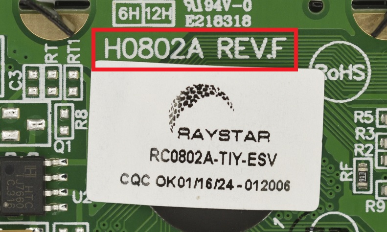
I noticed however that there was another name/number than RC0802A printed on the PCB, H0802A:

I googled this and found a datasheet on some shady site for an LCD module with this name. That turned out to be a 5 V model, and I started comparing two two datasheets. One thing I quickly found was that pin 3 that was listed as a no-connect in RC0802A datasheet was very much a pin that needed to be connected according to the H0802A datasheet.
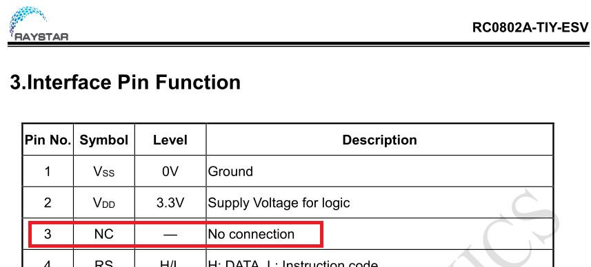
LCDs like these normally require an LCD bias voltage to be applied to pin 3 to set the contrast, but the RC0802A-TIY-ESV datasheet was very clear that pin 3 in this case was a no connect:

Not so on the H0802A:

So, in some kind of desperation, I hooked up a 22 k potentiometer between +3.3 V and 0 V with the center pin connected to the supposedly “no connect” pin 3 of the RC0802A. To my relief, it was now possible to find a potentiometer setting that resulted in visible characters!
I measured the voltage on pin 3 with the pot set to give a good contrast and it turned out to be -1.3 V, a strange output voltage of a divider between +3.3 V and 0 V. To allow as low a supply voltage as 3.3 V, the LCD module has an internal charge pump (a version of the classic ‘7660) that creates -3.3 V and there is apparently a 4.7 k pulldown (R5) between -3.3 V and pin 3. Unfortunately, they have forgotten (?) to add the other part of the voltage divider to 0 V to create an LCD bias voltage that results in visible characters.
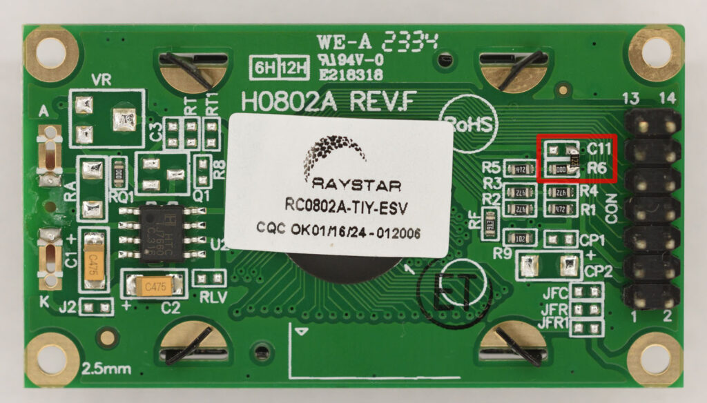
Anyway, I disconnected the +3.3 V terminal of the potentiometer, resulting in a rheostat between 0V and pin 3 and adjusted the pot to give a good contrast on the LCD. The resistance turned out to be about 1.2 k. After some inspection (and ohm-measurements) on the LCD, I found that it would be be relatively convenient to add a 1.2 k 0603 resistor between a pad of R6 and another of the (not mounted) C11:

With this patch, the LCD works fine, without me having to patch the PCB I had already designed where this LCD plugs in. Placing the patch resistor between pins 1 and 3 on the connector on either the LCD or on the main PCB where it plugs in is of course also an option.
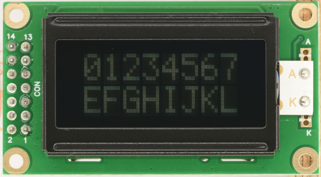
This is what the display looks like with the 1.2 k resistor in place:

Very strange that the Raystar RC0802A-TIY-ESV datasheet explicitly says that pin 3 is a no-connect, whereas it is crucial that it actually gets properly connected to produce visible characters.