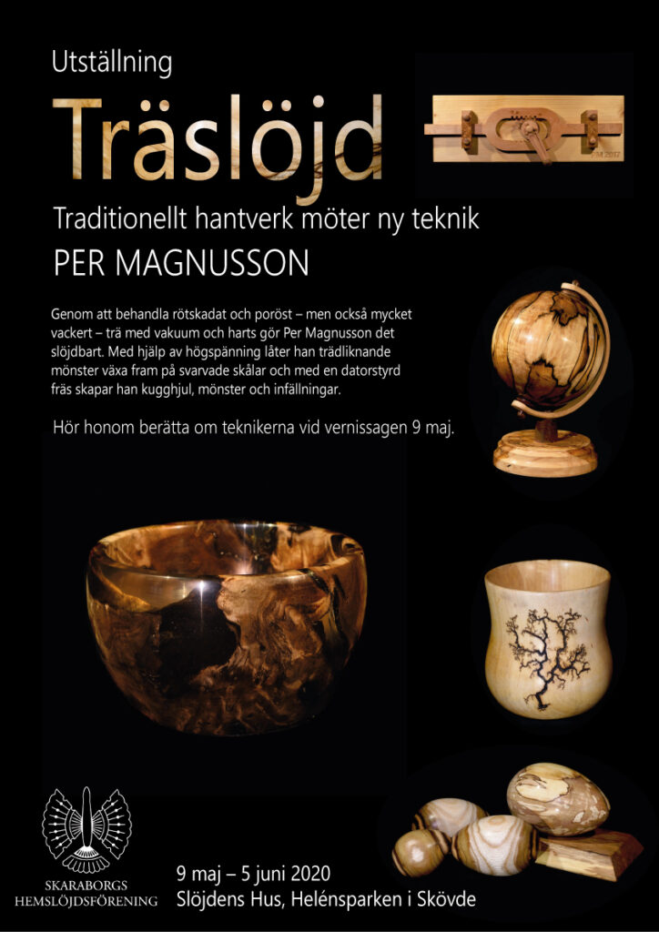
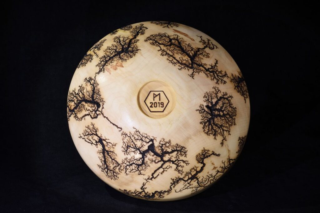
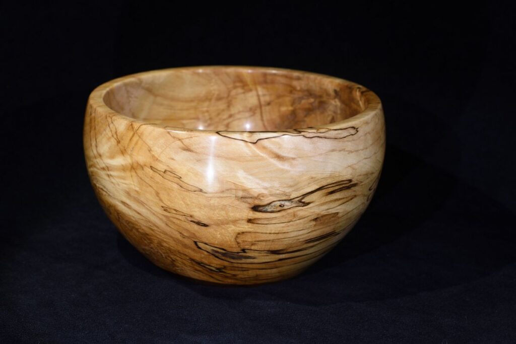
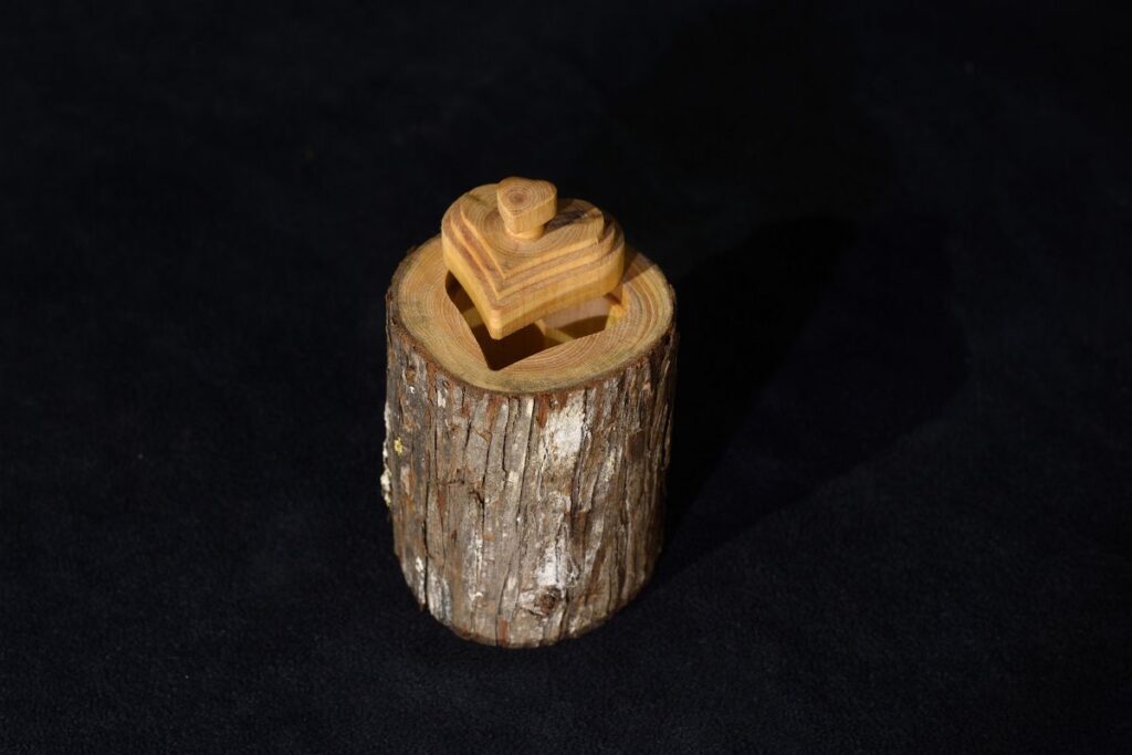
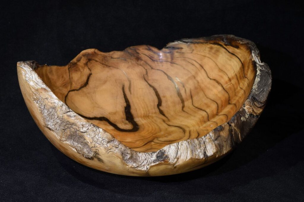
Den 27:e mars till och med 24:e april pågår min utställning av träslöjdsföremål på Slöjdens hus i Skövde. Temat är: “Traditionellt hantverk möter ny teknik” och jag visar bland annat upp föremål som vakuumstabiliserats, datorfrästs eller fått Lichtenbergfigurer med hjälp av högspänning.
Här är en film som demonstrerar dessa tekniker. Filmen visas även i utställningslokalen och är med flit ljudlös.
En digital vernissage hålls på Facebook den 27:e mars kl 11:
Uppdatering 1/4: (Nej, det här är inget aprilskämt.) På grund av det rådande läget med corona-pandemin så måste vi tyvärr ställa in den planerade utställningen. Förhoppningsvis kommer den att hållas någon gång våren 2021 istället.
Den 9:e maj till 5:e juni har jag en utställning med träslöjdsföremål i Slöjdens hus i Skövde. Bland de tekniker jag använt märks vakuumstabilisering av rötskadat trä, användning av datorstyrd fräs samt etsning av Lichtenbergfigurer med hjälp av högspänning.
I recently bought a used Taig desktop CNC mill, primarily to use if for making front panels in aluminum and plastics and for learning how to use a CNC mill. It can also be useful for milling PCBs from copper clad boards.
A special use is for depanelizing PCBs ordered from cheap hobbyist friendly PCB manufacturers in China. I recently learned that you need to pay a lot extra if you put several PCB designs within the board perimeter and ask the factory to mostly separate the designs using mill lines. If instead there are few or no internal mill lines within the board files sent to the manufacturer, you just pay the advertised price for that size board and avoid the extra multi-design charge. But then you need to saw the boards apart, or better yet, use a CNC mill to do the depanelization.
Taig CNC mill
It has been great fun learning how to use this thing and I am very happy with the purchase so far. There were lots of things I did not know about the process of using a CNC mill before I got started. A major thing is to figure out a “tool-chain” to go from design idea to making the mill move.
DraftSight, CamBam and Mach 3
Initially I used the 2D CAD program DraftSight to create DXF files, which I then imported into a program called CamBam. Inside CamBam, parts of the geometry of the DXF drawing is selected and one instructs the program what to do with it, like mill a pocket inside a closed contour, drill a hole inside a circle, engrave a contour or mill around the outside of a contour. There are many parameters to set up, like what mill tool to use, at what speed to move the tool, how deep each cut should be, how to transition to deeper levels and so on. The output of CamBam is gcode, a simple language similar to gerber that instructs the mill how to move. The gcode is then read into a program called Mach 3 that controls the mill. An old computer running Mach 3 was included with the mill and it was properly set up, so I did not need to configure it to fit this particular mill.
This process worked out pretty well, until the demo version of CamBam – that was supposed to work 40 times before one needed to buy a license – refused to work after about 10 runs. I was very close to buying a license for €108, but then I found on Youtube (I think) that there were other options…
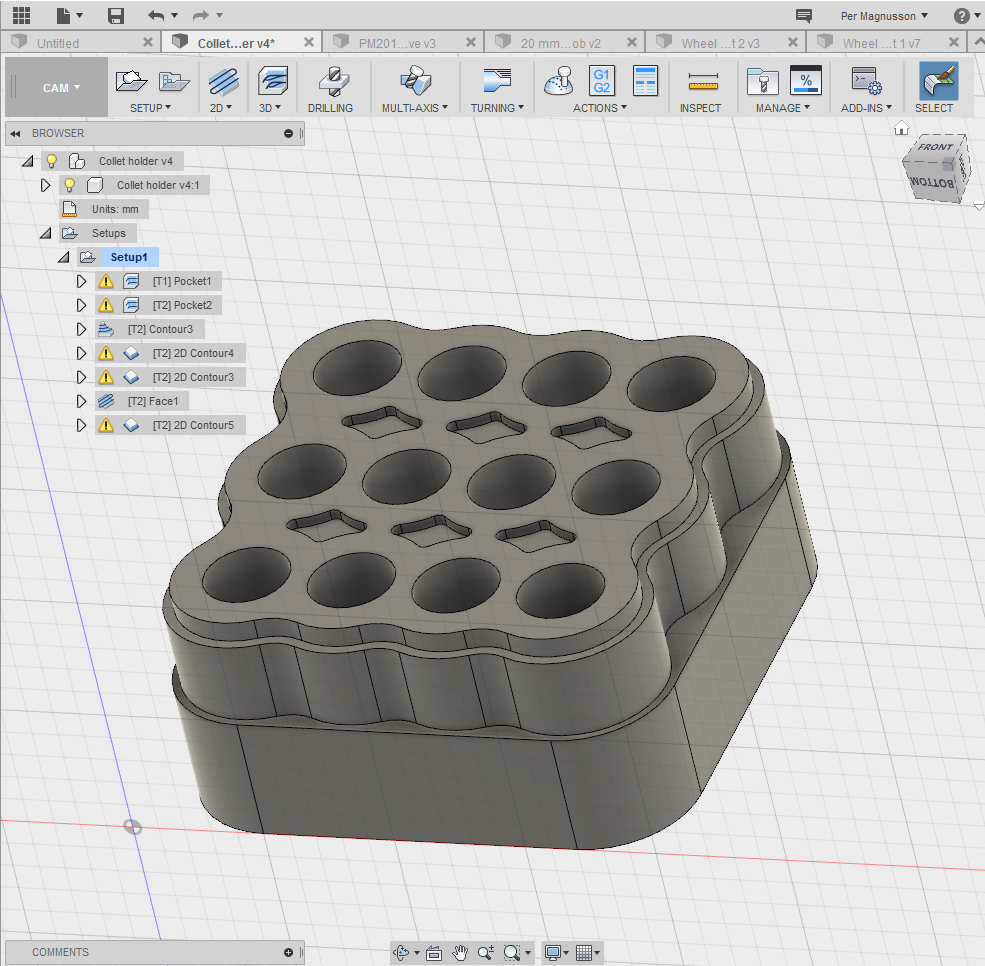
Fusion 360 and Mach 3
Autodesk offers a 3D CAD program called Fusion 360 and it is free, at least for a year, for hobbyists and small companies. Not only is it a CAD-program, it also includes CAM (computer aided manufacturing) functionality, so that it can generate the gcode directly. It also seems more capable than CamBam in terms of CAM features. The CAD part feels less powerful than SolidWorks (which I have recently started using at my daytime job), but it seems to be more than capable enough for what I want to do with the mill.
Screenshot of Fusion 360
Learning enough of Fusion 360 to be able to produce gcode for a few reasonably simple objects was fairly quick. I probably was a little helped by having done a bit of 3D CAD in SolidWorks, OnShape and other programs, but I had to learn the specifics of Fusion and especially how to do the CAM part. I did this mostly through googling and watching a few Youtube videos.
Lessons learned
For practice, I have made a few parts out of wood. There seems to be a lot of experience required to make the perfect CAM processing specifically for different kinds of wood, but I am getting there. It is easier to get good results requiring little manual post processing (like sanding and trimming) when using hard wood (like beech) than when using soft wood (like pine or spruce).
I found out that by running a finishing pass on most surfaces, milling higher levels after lower levels (when possible) and finally facing any flat top surfaces, one can minimize the amount of manual work required.
Another issue that is critical is work holding. It is very easy to set up the work piece in a way such that it moves a little (or a lot…) during the milling operation. This of course ruins the result. Quite a bit of ingenuity can be required to figure out how to secure the stock to the moving table.
Sample project
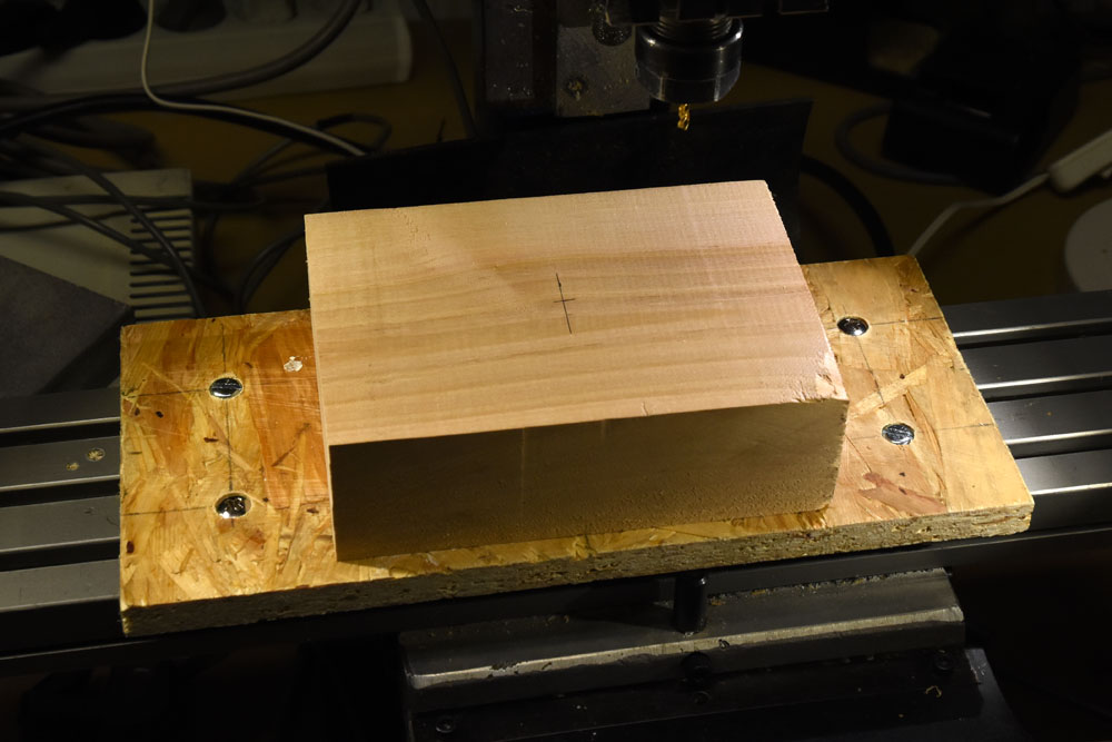
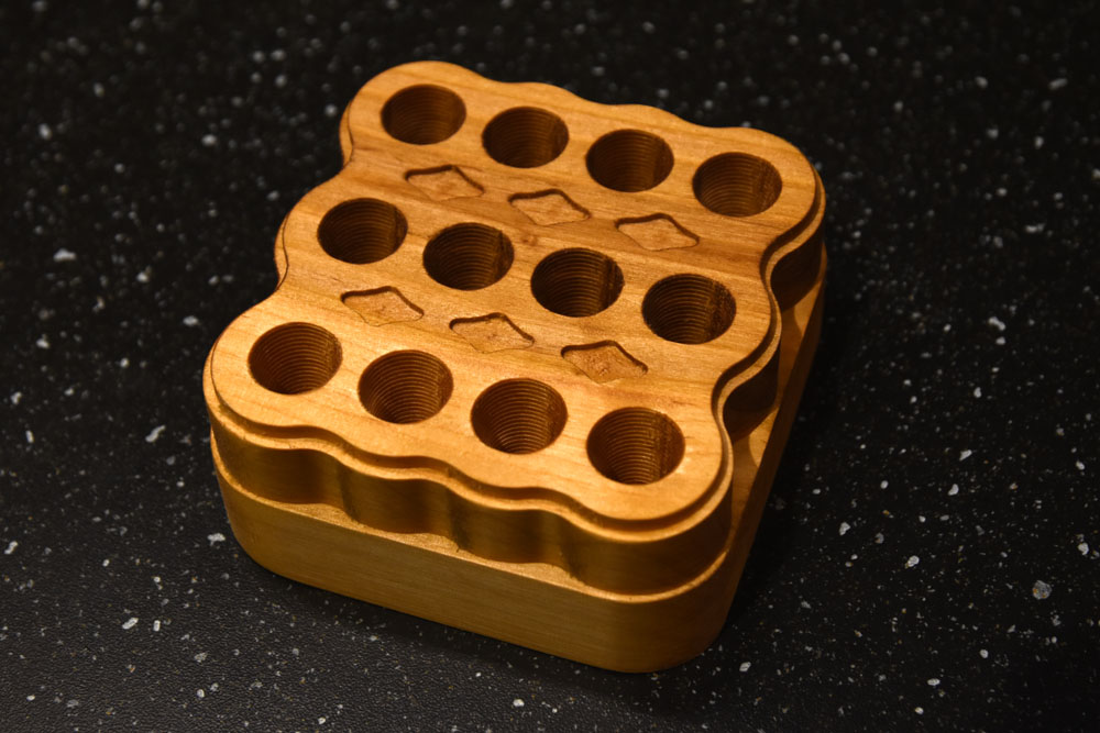
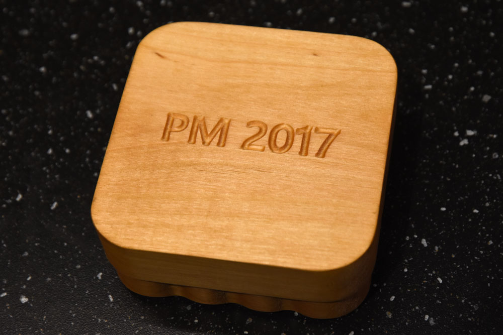
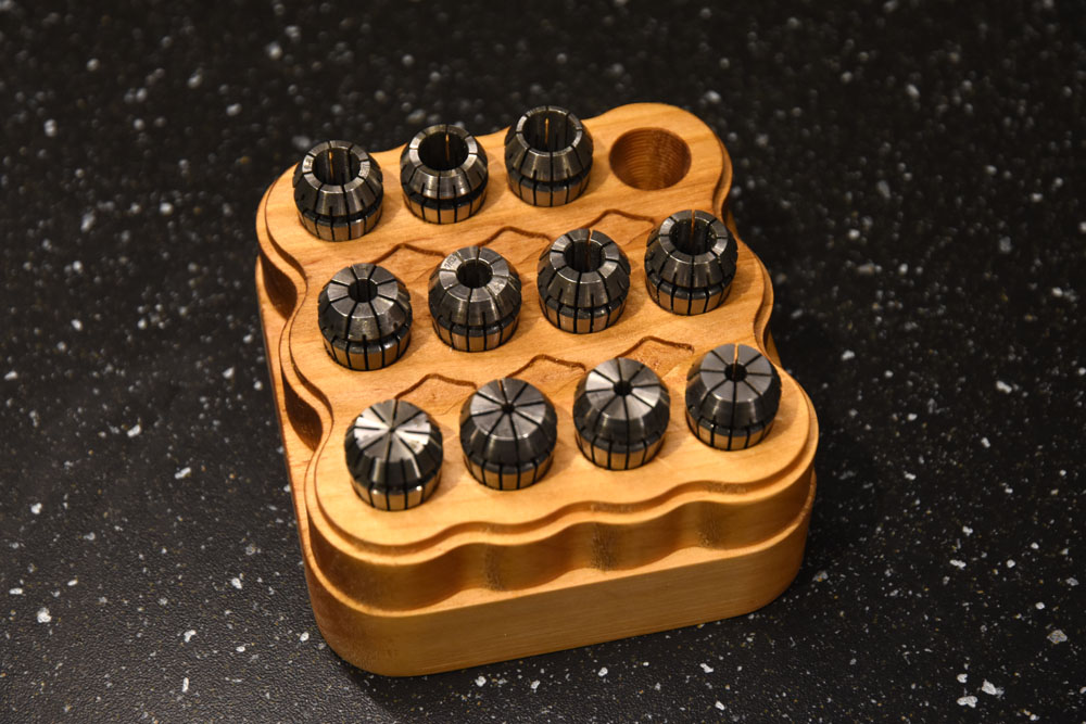
Below are a few pictures of a stand I made to hold the collets for the mill. It is made of some kind of quite soft wood, but by running finishing passes on some of the surfaces (inside the tapered holes and on the top surface), not too much sanding was required.
Below is a series of pictures showing how this piece was made.
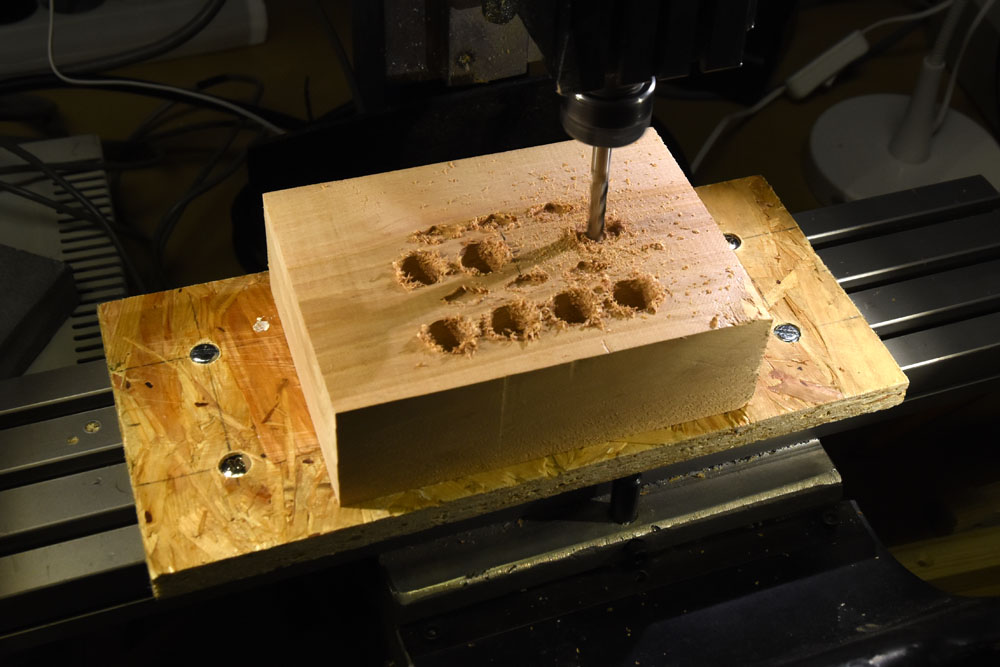
The starting stock. It is attached to the OSB board from underneath by screws in the corners. The OSB board is held to the XY-table by the visible screws and T-nuts.
The decorative diamond shaped pockets have been milled by a 3 mm end mill and now the tapered holes are being milled by a long 6 mm end mill.
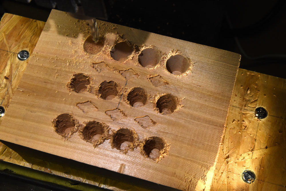
The finishing pass of the holes is in progress. The three holes to the right in the upper row have received their finishing pass.
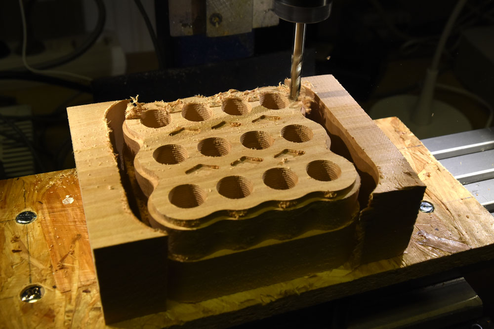
The outside contour is half finished and the top surface facing is in progress.
The finished piece. The remaining tabs that held it to the sacrificial outer parts towards the end of the milling have been sawed off and sanded down. The part has also been oiled.
The engraving on the bottom was done using a 2.5 mm ball nose mill.