Background
In recent years, I have been using Arduinos and Teensys with the Arduino environment and FRDM boards using the mbed web-based environment for small processor-controlled projects. However, when doing a project with a custom PCB that includes the processor, these platforms and environments are no longer quite as attractive.
Sure, one can use the same processor as exists on some Arduino and program it with the proper Arduino bootloader and continue working in the Arduino environment. Or one could use e.g. an STM32 processor that exists on one of the boards supported by mbed and program it via the ST-link of such a board. But when moving away from exactly the processor variants that exist on mbed-supported boards, one might run into trouble as ordinary users do not seem to be able to configure the mbed environment for other processor variants. Also, the fact that mbed resides in the cloud could be downside depending on personal preferences.
For these reasons I wanted to set up a local development environment so that I could use some reasonably modern 32-bit ARM processor on a fully custom board. I also wanted a solution that did not cost any money, so Keil and IAR are out of the question. I opted to use STM32L052C8T6 from the the STM32 L0 family of low-power Cortex M0+ parts as it seemed to have the features and performance I needed while also being power efficient and thereby possibly supporting battery operation at some future version of my design. An advantage of STM32-processors from ST is that they can be programmed via the ST-Link that is built into every inexpensive (~$10-15) Discovery or Nucleo development board. So no expensive programmer is necessary.
There seems to be more than one option for free development environments for STM32 processors and I first tried to set up Eclipse with the GNU ARM Eclipse plugins. After a lot of time reading various posts on the GNU ARM Eclipse website and installing all the bits and pieces I still was not able to compile the configuration and initialization code generated by STM32CubeMX. Probably someone with more experience, patience and knowledge of Eclipse than me could get this to work, but after a lot of fiddling around with settings of include and code directories I tried another option, namely the SW4STM32 environment provided by the company Ac6.
Tool installation
SW4STM32 is a free (but requires registration) tool based on Eclipse. Although I use it on Windows, it is also available for Linux and MacOSX. I guess most of the below instructions apply for non-Windows installations as well.
This is how to install SW4STM32:
- Create an account on http://www.openstm32.org/HomePage and log in.
- Follow the instructions under Documentation > System Workbench for STM32 > Installation manual, or continue below.
- Download the appropriate (32-bit or 64-bit version) of the installer from http://www.openstm32.org/Downloading+the+System+Workbench+for+STM32+installer. It is important to select the correct architecture (32/64) to make the ST-Link debug probe work.
- Run the installer.
- If you get a warning about JavaRE, you need to install the appropriate Java runtime from Oracle. It has to have the same architecture (32/64-bit) as SW4STM32.
- Click through the dialogs. Select C:\Ac6\SystemWorkbench or some other suitable path without spaces in the folder names as installation directory.
- Launch the program when the installation is finished and go to Help > Check for updates to update to the latest version of all the components.
To get started with the software development, one can use the tool STM32CubeMX from ST to generate configuration and initialization code:
- Download STM32CubeMX from http://www.st.com/content/st_com/en/products/development-tools/software-development-tools/stm32-software-development-tools/stm32-configurators-and-code-generators/stm32cubemx.html
- Install the tool.
It is not immediately obvious how to use CubeMX such that the resulting code is easily imported into SW4STM32. I learned this the hard way, but found the solution on: http://www.openstm32.org/Importing+a+STCubeMX+generated+project.
Here is how to do it:
- Create a project catalog, e.g. D:\Projects\STM32.
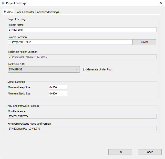
- Open CubeMX and open the menu Project > Settings…
- Enter a project name (e.g. “STM32_proj”).
- Change project location to the previously created catalog (e.g. D:\Projects\STM32).
- Change the Toolchain / IDE to SW4STM32
- If you have a previously started project, these fields are not editable. Select “Save Project As…” to be able to edit the fields.
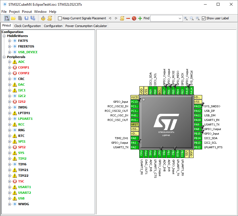
CubeMX settings - Set up all the pins and peripherals in CubeMX and generate the code (Project > Generate Code).
- Open SW4STM32 (e.g. by double clicking on C:\Ac6\SystemWorkbench\eclipse.exe ).
- Select D:\Projects\STM32 as workspace.
- File > Import… > General > Existing Projects into Workspace > Next
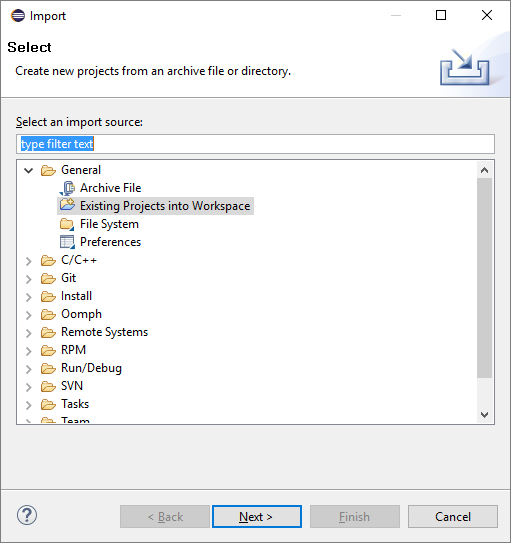
- Browse for D:\Projects\STM32 as root directory. The project STM32_proj should be detected and selected.
- Do NOT check the option “Copy projects into workspace”.
- Click Finish.
Unfortunately, the project did not compile for me even after these maneuvers. I found the solution at http://www.openstm32.org/tiki-view_faq.php?faqId=4#q21:
The trick is to tell SW4STM32 to not parse files that are not used by the project. This is how to do that:
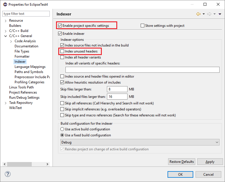
- Select Project > Properties > C/C++ General > Indexer
- Check “Enable project specific settings”
- Uncheck “Index unused headers”.
Getting to blinky
To quickly test that I could get all the way to code executing on the processor I added a simple LED-blinking routine inside the infinite while loop in the CubeMX code (I had LEDs on PA15 and PA7):
  /* Infinite loop */
  /* USER CODE BEGIN WHILE */
  while (1)
  {
  /* USER CODE END WHILE */
  /* USER CODE BEGIN 3 */
      HAL_GPIO_WritePin(GPIOA, GPIO_PIN_15, GPIO_PIN_SET);
      HAL_GPIO_WritePin(GPIOA, GPIO_PIN_7, GPIO_PIN_RESET);
      HAL_Delay(200);
      HAL_GPIO_WritePin(GPIOA, GPIO_PIN_15, GPIO_PIN_RESET);
      HAL_GPIO_WritePin(GPIOA, GPIO_PIN_7, GPIO_PIN_SET);
      HAL_Delay(200);
  }
  /* USER CODE END 3 */
“Project > Build All” generated a .bin file in the Debug catalog under the project folder. I configured my ST-Link for talking to an external board and connected it to my target board.
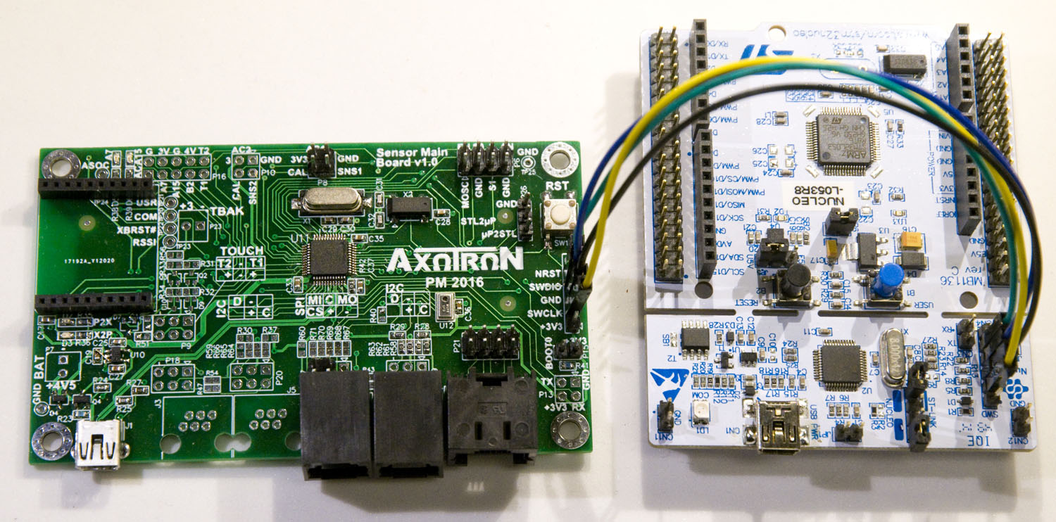
Then I connected both boards via USB cables to the computer and dragged the .bin file to the “NODE_L053R8” drive that the ST-Link appears as. The programming worked and the LEDs started blinking!