An I2C bus (or SMBus) can fail to work for various reasons. A well known reason is that there may be too much capacitance on the bus causing too slow low-to-high transitions. 400 pF is the maximum bus capacitance according to the I2C specification, but this is not necessarily a hard limit in practice. The problem of excessive capacitance can often be remedied by lowering the data rate, decreasing the value of the pull-up resistors or somehow reducing the bus capacitance by changed routing, shortened cables or using a different kind of cable.
This article however describes a different and perhaps less obvious problem that can occur while running an I2C bus in a cable, namely crosstalk, and what to do about it, if it becomes a problem.
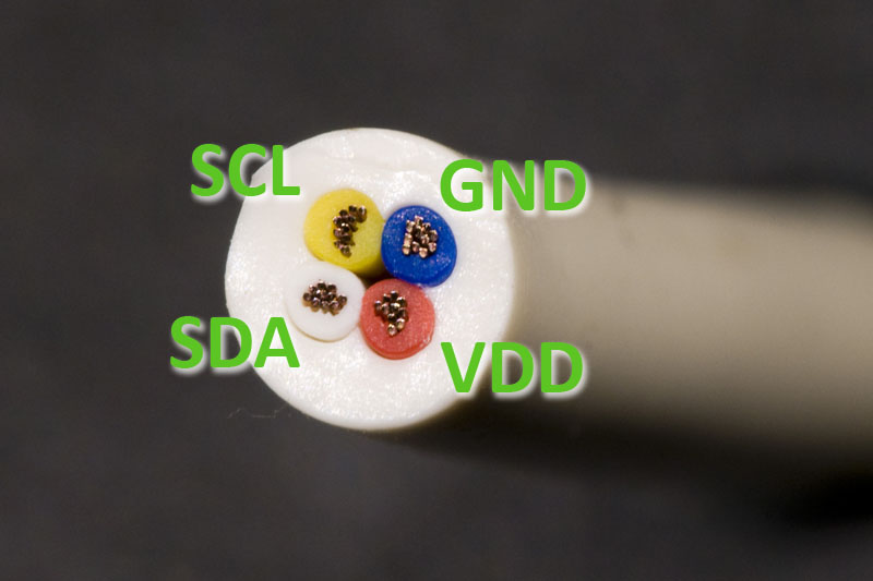
Here is a photo of the cross section of the simple telephone cable used in the experiments in this article. The labels show the initial signal assignment that were used to provide both power and an I2C bus to a temperature sensor.
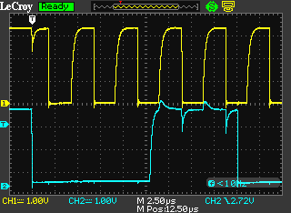
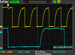
4.7 kohm were used as pull-up resistors. Below is a scope plot of the resulting signals when using 70 cm of cable and a data rate of approximately 200 kHz.
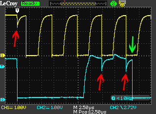
The red arrows show where one signal is disturbed by a fast transition from high to low on the other signal. The green arrow shows that no disturbance can be seen on SCL when SCL is low, despite the fast transition from high to low on SDA. The reason that the signals are only disturbed while they are high is that in the high state, it is only a relatively weak pull-up resistor that keeps the signal at its proper level, so a small amount of current injected into the signal can change the voltage quite a bit. When an I2C signal is low, it is held low by a strong transistor which has an on-resistance of only a few tens of ohms so it would require a current that is two orders of magnitude stronger to cause a disturbance of the same amplitude on a low I2C signal than on a signal in the high state.
If the negative going glitches caused by the crosstalk become large enough, they may cause the bus to fail in various ways as the signals are misinterpreted, so it is important to keep these under control. The I2C specification defines valid high logic levels as being at least 70% of VDD. 70% of 3.3 V is 2.31 V and the glitches in the plot above dip down to this level, which is bad.
Coupling mechanism
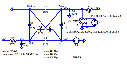
The mechanism for coupling from the disturbing signal (the aggressor) to the disturbed signal (the victim) is the capacitance between the wires in the cable. A schematic model of the I2C-bus and cable (drawn using LTspice) is shown below.
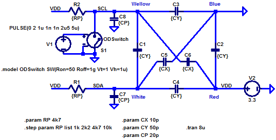
R1 and R2 are the I2C pull-up resistors. C1-C4 are the capacitances between adjacent wires in the cable while C5 and C6 are the capacitances between the diagonal wires. C7 and C8 are stray capacitances on the PCBs as well as capacitances at the pins of the ICs. S1 is a switch that models the open-drain output of the driving pin while V1 controls when the switch is closed and when it is open. The values of several of the components are set as parameters (within curly braces) to make it easier to modify them and adapt them to the actual values of a specific instance of the circuit. The capacitances shown in the schematic are reasonably representative of the real circuit discussed above.
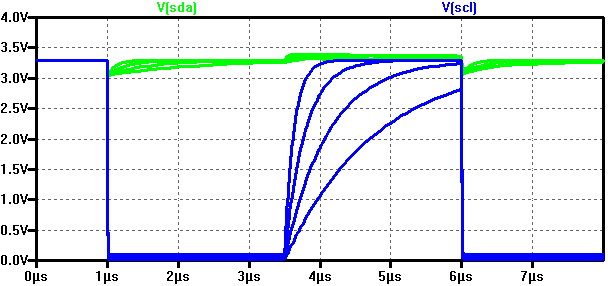
Below are the simulated waveforms of the SCL and SDA signals when the I2C pull-up resistors are stepped from 1k via 2k2 and 4k7 to 10kohms.
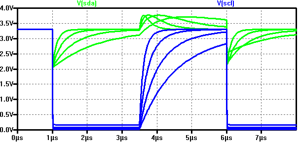
One can note that the amplitude of the glitches and the steepness of the edges match the measurement pretty well for the 4k7 pull-up resistor (the next slowest traces). This supports that the model is fairly accurate.
We can see that the initial glitch in the SDA waveform has (almost) the same amplitude regardless of the the value of the pull-up resistors. This might not be expected, but is a consequence of the fact that the initial part of the step is dominated by the capacitive voltage division in the circuit. The capacitive divider consists of C1 which injects charge into the parallel combination of C4, C5 and C7. Right after the step, the voltages on the capacitors start to recover and how quickly this happens is determined by the value of the pull-up resistor, so the 1k resistor gives a ten times quicker recovery than the 10k resistor. But note that it does not significantly reduce the magnitude of the glitch.
There is also a little crosstalk happening during the slower positive edge of the aggressor. This crosstalk is much less of a problem since it has a positive amplitude and thus either increases the already positive amplitude of the victim signal or does not affect a low victim signal since that is actively being pulled low and is thus almost immune to the disturbance.
Reduced pull-up resistances
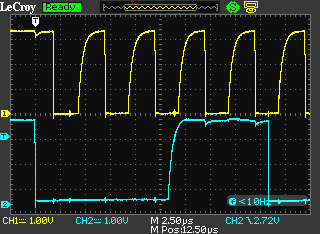
A lower value of the pull-up resistors did not seem to do much good according to the simulation, but let’s anyway verify this in reality. Below is the same measurement as before, but with 2.2 kohm pull-up resistors.
As predicted by the simulation, the amplitude of the glitches remain the same, while the positive edges have become steeper.
Modified cable configuration
So, we could not reduce the amplitude of the crosstalk by the old standard trick of reducing the pull-up resistance. So is there something else that we can try?
Since the coupling mechanism is capacitive, we would like to reduce the capacitance between the aggressor and victim. This can actually be done without changing cables if we change which wire is used for what signal. To do this, the I2C signals are put on diagonal instead of adjacent wires as follows:

(If it had instead been a four-wire ribbon cable, putting the I2C signals on the outer wires and power and GND on the two inner had been the way to go. In a twisted-pair cable, the I2C signals should be twisted with power or GND and absolutely not with each other.)
The resulting crosstalk is shown in the plots below for 4.7k and 2.2k pull-ups.

As can be seen, the glitches have been substantially reduced and are now harmless. This can also be simulated by just changing the simulation schematic slightly to move the aggressor diagonally from the victim:
The resulting waveforms are shown below.
The simulation matches the measurement well also in this case.
So the method of placing the I2C signals far away from each other in the cable is apparently effective, just as expected.
A less elegant possibility is to add more capacitance between the I2C signals and GND, provided the bus capacitance is not already too large. This will affect the capacitive voltage division in a positive manner and reduce the crosstalk by increasing the capacitance from victim to GND instead of reducing the capacitance between aggressor and victim. The cable reassignment above actually did both reduce the aggressor-victim capacitance as well as increase the victim-to-GND (and power) capacitance, so it made use of both mechanisms.
Cable length influence
Another question is how the length of the cable affects the crosstalk. By examining the schematic models of the cables, one can realize that all the cable capacitances (C1-C6) are proportional to the length of the cable. As mentioned above, the amplitude of the crosstalk is controlled by capacitive voltage division. All of the capacitances involved in the division, except for the small external capacitances to GND (C7 and C8), grow linearly with the length of the cable, so as long as the cable capacitances dominate over the stray capacitances to GND, the length of the cable should have only a very minor impact on the amplitude of the crosstalk.
Below is an oscilloscope plot of an I2C bus that is run through 2.7 m of cable.
As expected, the amplitude of the crosstalk has remained essentially the same while the edges are less steep due to the added capacitance.
Summary and recommendations
- I2C is particularly sensitive to capacitive crosstalk since the signals are often not driven by strong drivers, but instead by weak pull-up resistors.
- Glitches caused by crosstalk can cause an I2C bus to malfunction.
- Cables often have a large capacitance between at least some of the wires.
- Reducing the value of the I2C pull-up resistors does not have any significant effect on the crosstalk and is therefore not an effective way of controlling it.
- I2C signals should be placed in a cable such that they have as little capacitance as possible to aggressor signals, i.e. to signals with fast high-to-low transitions (like other I2C signals).
- Capacitance between I2C wires and power and GND wires help reduce crosstalk (but at the expense of higher bus capacitance, and thus slower transitions and reduced maximum speed for a given value of pull-up resistor).
- In twisted pair cables, the I2C signals should be paired with power or GND wires, not with other I2C signals.
- In ribbon cables, the I2C signals should only be adjacent to power or GND wires.
- The length of the cable does normally not affect the amplitude of the crosstalk very much. (As long as the cable is long enough so that the cable capacitance dominates over other bus capacitances.)
- Longer cables do of course add more capacitance and thus reduce the steepness of the positive edges, which can reduce the maximum speed and/or require reduced pull-up resistances.
- It is a very good idea to use an oscilloscope to take a look at the I2C signals in any new design to see if they look good or need to be improved.
I hope this article has provided some intuition about – and insight into – I2C crosstalk in cables and what to do to control it.