Monthly Archives: December 2013

Multimeter repair

This is a story about troubleshooting and repairing a multimeter.   A technique on how to locate a short is described.

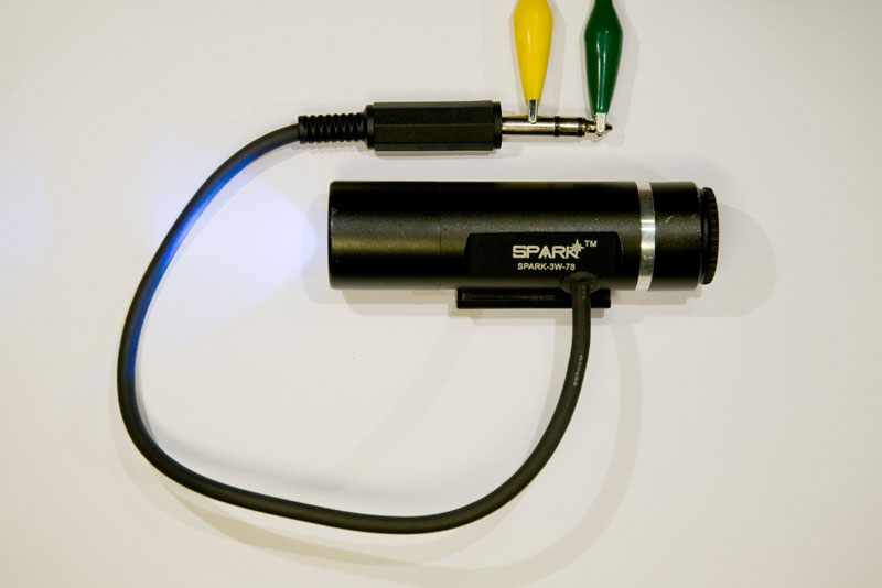
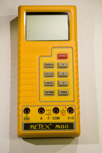
So, I was working on a project in the lab and needed to measure both voltage and current simultaneously, so I brought out an extra digital multimeter (DMM) I had on a shelf, a Metex M80. Unfortunately, nothing happened when I pushed the power button. Well, it had been unused for probably over a year, so maybe the battery was shot. I checked the 9 V battery and it measured 7.5 V or so. That should be enough to power the multimeter. Strange.

Metex M80
A dead Metex M80 multimeter.

I then checked the battery voltage while connected to the  DMM and now it was 0 V. Even stranger. Had the internal resistance of the battery become so large that the tiny current of the multimeter brought the voltage down to zero? That seemed unlikely, but I tried with a brand new battery and still got 0 V while trying to power the DMM. Not good. The instrument seemed to be shorted, and sure enough, the resistance across the DMM battery connector was 0 Ω while the power button was switched on.

Time for more serious troubleshooting.

I took the instrument apart and found a 2-layer PCB inside. My standard technique for finding where the short is between two conductors on a PCB is to use a lab power supply to inject a current (a few hundred mA typically, with voltage limited to 0.5 V or less to prevent damage if the short suddenly goes away) and measure voltage drop along the tracks. This is effectively four-terminal sensing, or Kelvin sensing where the test current is applied through two leads and the voltage drop is measured using separate leads; unlike how a common two-terminal ohm-meter works.

The current obviously flows from the lab power supply, through some tracks on the PCB, via the short, through some other tracks on the PCB and back to the supply. Wherever current is flowing through a finite resistance, there is a voltage drop (Ohm’s law) and although the copper tracks are pretty good conductors, a current of a hundred mA or more  will typically cause a voltage drop of at least a few mV, which can be easily measured.

So, by measuring the voltage drop across the tracks, it is possible to figure out where the current is flowing and thus where the short is located. If you put one probe on the point were a wire from the lab supply enters the board and you measure the voltage drop to various points along a track further and further away from the reference point, the voltage drop will be gradually higher and higher as long as the current is flowing in the track you are following. If the track branches (or if there is a component pin connected to it) and the voltage stays the same beyond the fork, you can conclude that the current is flowing in the other branch. This is perfect for figuring out where the short is located.

(As a side note, the same technique also works for boards with power and ground planes, although you might need to use more current and/or a more sensitive voltmeter due to the very low resistance of the planes. I have on a number of occasions located shorts between power and ground planes on multi-layer PCBs to with in a few mm.)

Below is a series of pictures showing how I applied the method in this case.

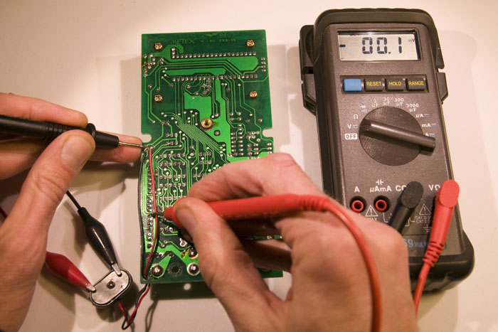
First I followed a track going south from the negative terminal. The voltmeter reads -0.1 mV (0 mV is well within the error bars here), so the conclusion is that this is not the way the current is flowing.

Measuring voltage drop
Measuring the voltage drop across a PCB track. No current seems to be flowing this way.

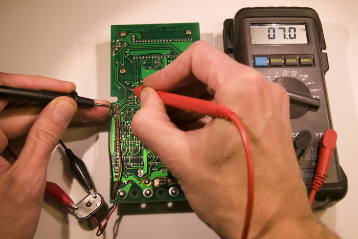
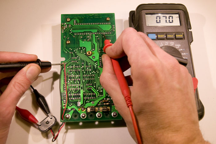
Then I followed the track north to the first fork, which happened to be a component pin. Here we can see a significant voltage drop of 7.0 mV, so current seems to be flowing in this track.

Measuring voltage drop
Here we see a voltage drop of 7 mV, so current seems to be flowing in this track!

The track continues north and then turns east to another component pin, but the voltage is the same here, so the conclusion must be that the current came from the component pin in the previous measurement.

Measuring voltage drop
No further voltage drop despite a long piece of track since the last point. So the current came from the pin in the last measurement and not from up here.

The pin with the current belongs to an electrolytic capacitor on the other side of the board. See photo below.

The suspect electrolytic capacitor,

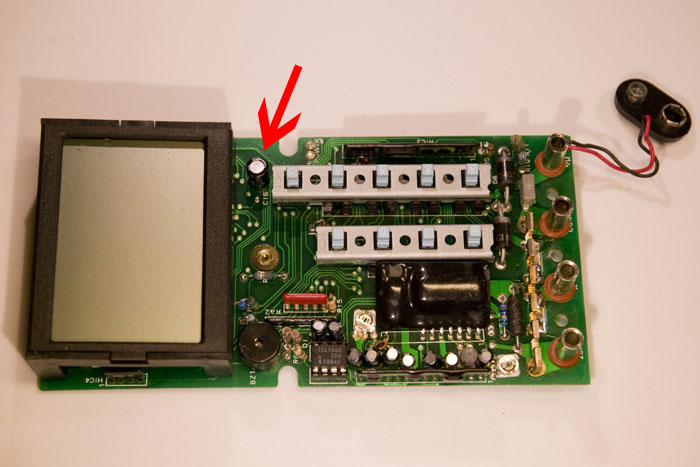
Electrolytics are notorious for their degradation over time, so it is not too surprising that this component has failed. Especially since it turns out to be rated at +85 °C (good electrolytics are rated for at least 105 °C). It also has a voltage rating of  just 16 V, which does not provide a lot of margin as it is exposed to the voltage of a 9 V battery. It seems like the manufacturer of this DMM aimed for low cost rather than high reliability.

Replacing the capacitor was simple enough and, as expected, the removed component was internally shorted. After the replacement the short was gone and the multimeter worked!

Working multimeter
It’s alive!

So now I can go back from this detour to the project I was working on. Or rather, that will have to wait until tomorrow.

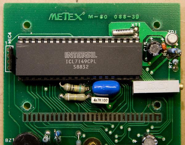
Update on 2014-02-23: Branko asked in the comments about what IC is in the M80 and it turns out it is an ICL7149CPL. Below is a photo of it.

The main IC of the M80, and ICL7149CPL.
The main IC of the M80, an ICL7149CPL

Simple Dynamo Powered Bicycle LED Light

After the incandescent bulb of the bicycle light broke for the second time in a few weeks, I thought it was time to retire Edison’s invention and move into the 21st century by replacing it with an LED.

I had a cheap battery powered bike LED light laying around, but I wanted the LED to be powered by the hub dynamo and so I decided to convert it from battery power to dynamo power. The dynamo generates AC current at a voltage and current that depends both on the speed of the bike and on the load that is connected to it, so some circuitry had to be designed and built to suitably drive the LED.

The bike light contained a battery holder for four AAA batteries, a single power LED and a small circuit board containing a glob-top chip, a decoupling capacitor, a small external MOSFET and a connection to a button that could put the LED in one of three modes: off, on and flashing. Text printed on the light said “3W”, but I doubt the LED can actually handle that much power and I also doubt the four small batteries could deliver the close-to-one-amp of current required for 3 W. 300 mA and thus approximately 1 W seemed more reasonable. As a hub dynamo can easily generate more than 300 mA and I wanted to get the full brightness at a reasonably low speed while still not overloading the LED at higher speeds, some form of constant current source was required.

If I had wanted to spend lots of time and development effort on building the perfect dynamo-driven bike LED light, I would probably have opted for a schottky bridge rectifier followed by an elaborate switch-mode converter driving one or more big LEDs, preferably with a control scheme that tries to maximize the power put into the LEDs at lower speeds, while keeping the power constant at higher speeds.

My priorities were however somewhat different with this project. I wanted a quick solution that I could finish in a few hours using components I had available at home. The solution I opted for was to build a bridge rectifier using four 1N4002s and follow it by an LM317 adjustable voltage regulator that drives the LED in series with a 1 ohm power resistor; see schematic below. By setting the output voltage of the LM317 to a suitable value, the 1-ohm resistor limits the current through the LED to the desired 300 mA.

Schematic for constant current bike LED light.

I first measured the LED voltage at 300 mA of current and selected feedback resistors to the LM317 to get a little more than 0.3 V above that value (to account for the voltage drop across the current limiting resistor). That gave me the values for R1 and R2. Then I built the circuit on perf board, but without R3. After that I connected the LED (D5 in the schematic) and tested it while powered from a bench supply. I added R3 as required to reduce the current to 300 mA. Depending on what LED you have and how much current you want to supply it with, you need to adjust the voltage divider R1-R2-R3 accordingly.

The finished circuit board is shown below while fitted in the battery compartment of the original bike light. The LM317 does not get a lot of cooling, so maybe it will be get quite hot if pedalling fast. If that turns out to be the case, I will have to figure out a way to thermally connect it to the housing.

Top view of the electronics fitted in the battery compartment
Side view of the electronics as well as the original circuit board that is left in place.

I drilled a hole through the housing and fitted it with a grommet suitable for the cable I intended to use to connect the light to the dynamo. I used a 6.35 mm stereo plug and put a corresponding jack on the bike so that the light could be unplugged and removed. Hopefully these connectors are robust enough to work reliably outdoors for a few years. We will see. The photo below shows the finished light.

Test of the bike light using a bench supply hooked up to the 6.35 mm plug.

A quick test drive demonstrated that the contraption worked as intended. The light flickers when the bike rolls very slowly, but for any reasonable biking speed, the light is stable. Maybe I will build a more powerful bike light in the future, but for now this will do.