![[SW flag]](pic/Sw_flag_40.png)

![[UK/US flag]](pic/UK-US_flag_40.png)

|
|

Making Holders for Taped SMD ComponentsPublished 2012-03-18 Background![[Welded sheet protector]](articles/sheet_protector/fig01_protector.jpg)
Figure 1. A sheet protector modified
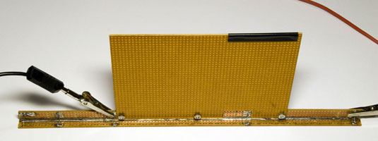
to hold taped components. There are some nice SMD component kits out there where the components are on cut tape and where the tapes are stored in binders containing special "sheet protectors" with pockets of suitable size for the tapes. An example is this 0805 kit sold by Adafruit. A problem is that not all kinds of taped components are available in such kits (I have e.g. not found any good kit with 0201 capacitors or 0201 resistors) and hence you might have a need to make a custom kit for yourself from cut tapes that you buy individually. It does however seem to be hard to find a source where sheet protectors with pockets for taped SMD components can be purchased, so there certainly is a problem with how to keep all the taped components in order so that they are easy to access. Keeping the tapes in labeled bags kept in (cardboard) boxes works, but is a bit awkward in terms of getting an overview over the stock and accessing the components. Another case where one might need the special sheet protectors for SMD components is to just keep order among the random taped components one accumulates after a few SMD projects. SolutionSo how can this problem be solved? I came up with the idea that maybe it would be possible to weld together sheet protectors to form suitable pockets. I did some initial experiments using a soldering station set to temperatures between 150˚C and 200˚C. This worked ok, but it took an inconveniently long time to complete a sheet since the soldering iron had to be dragged slowly over the plastics to get good welds. After some thought I came up with the idea of running (a lot of) current through a straight piece of metal to make it suitably hot for welding plastics. I had a coil of some steel band that looked promising and I measured the resistance of it (using the Kelvin method). It was 23 mΩ/m and I thought I needed maybe 20 W in 25 cm. This would mean about 60 A at 0.35 V; an inconvenient operating point. I actually started re-winding a mains transformer to get the required supply, but before I finished the rather tedious task, I came up with another idea, namely to use some much thinner and more resistive Kanthal wire supported by a 2.54 mm grid breadboard. I sew the wire up and down in a long strip of breadboard and attached connecting wires to it at strategic points to allow different lengths of wire to be heated at a time to make welds of various lengths. I also soldered another piece of breadboard at an angle to the first to make it sturdier. Then I found out that I needed to make it sturdier still and easier to hold without burning ones fingers, and so I bolted a third breadboard to the supporting strip of breadboard.
Figure 2. The plastics welder made from breadboard
and Kanthal wire.
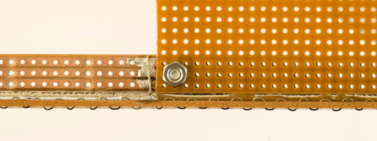
Figure 3. Side view of the welder showing the
resistive wire going up and down through the breadboard.
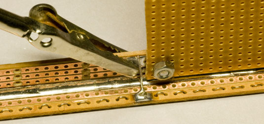
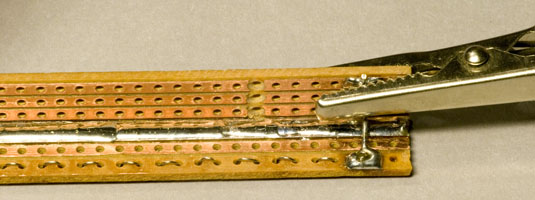
Figure 4. An alligator clip connected to one of the
terminals. The solderability of the Kanthal wire using normal flux is
approximately zero, so I wound the Kanthal wire two turns around the
copper wire and drenched the whole thing in solder, hoping that the
connection would be good enough. It actually seems to work.
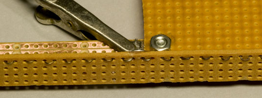
Figure 5. Close-up view from the bottom showing the
Kanthal wire protruding below the breadboard.
Figure 6. End terminal with alligator clip.
It turned out that about 1.6 - 2.0 A of current was suitable to form a good weld in a few seconds with the kind of wire I had used. This is of course much more convenient than 60 A and can easily be supplied by my lab power supply. As shown in the photos above, I use alligator clips to attach the cables to the welder. I connect the current when I want to create a weld and disconnect it a couple of seconds later just before removing the welder from the plastics. This way the temperature of the wire does not reach such a high temperature between the welds that the plastics that has inevitably stuck on the wire ends up as smoke. Attaching the clip after placing the welder on the desired place on the plastics ensures that the adjustments in the placement of the welder can be done without hurry to make sure that clean welds end up where they should. Warning: It is easy to over-heat the wire and maybe even cause a fire if too much current is run through it for too long a time. This simple design of a welder is not fool proof and has no protection from over-heating. Take care to not connect the current for more than a few seconds at a time. Choice of materialDifferent kinds of sheet protectors can be used as raw material for the component holders, but I decided to use special ESD-safe (low charging) sheet protectors in order to avoid the risk of electrostatically charging the tapes when extracted from their pockets. If you do not care so much about ESD, you might instead use cheaper and more easily available normal office sheet protectors, but do this at your own peril as you increase the risk of zapping some expensive chip, maybe creating a latent fault that will not show up until much later. Producing the component pocketsTo facilitate the "manufacturing", I have printed out a template grid to guide me where to place the welds (or rather where to place the edge of the welder). The grid was made in Excel and a copy of it (suitable for A4 size sheets) can be found through this link:
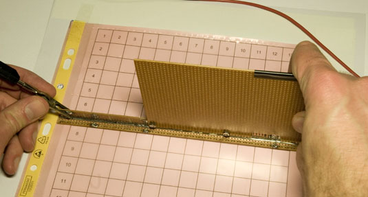
I have taped this grid to a larger sheet of paper to which I tape the sheet protector to be processed in order to keep it fixed during welding as shown in figure 7 below.
Figure 7. A grid to guide the welding.
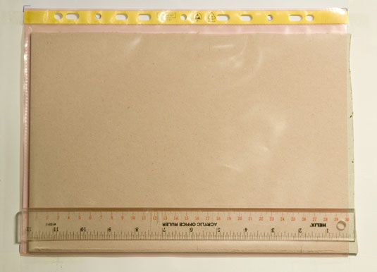
Before welding, it is a good idea to cut slits in the top plastics sheet so that one has some way of inserting the component tapes. This is necessary at least if horizontal pockets are to be made, but also for vertical pockets it is useful to cut off a little bit of the top part of the top plastic sheet to make it easier to insert the tapes. I do this step by inserting a cardboard sheet in the sheet protector and cutting the slits with the help of a ruler as shown in figure 8 below.
Figure 8. A ruler and a cardboard sheet to help when
cutting a slit in the top plastic sheet.
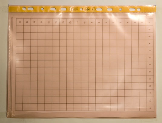
When the sheet protector has been cut as desired, it is taped on top of the grid to make it easy to weld as shown in figure 9 below. It is best to offset it so that the edge of the welder can be aligned with the grid, rather than trying to align the actual welds with the grid.
Figure 9. The cut sheet protector taped to the
grid, ready for welding.
Figure 10 below shows how the welder is held when forming the welds.
Figure 10. Holding the welder while welding.
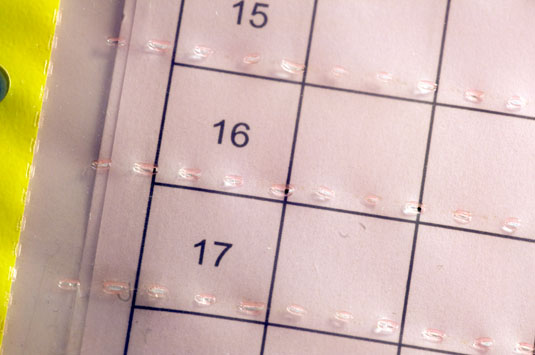
A close-up of the resulting welds can be seen in figure 11 below.
Figure 11. Close-up of welds.
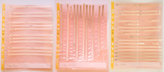
Organizing the component tapesDepending on the lengths of ones cut component tapes, different configurations of the tape holders might be suitable. I have tried a number of different variants (see figure 12 below), but the one I currently like the most is the one with horizontal pockets and a slit in the middle as well as one to the right. Horizontal pockets allow more pockets to be formed on the same sheet and the slit in the middle allow short pieces of tape to take up only half the width of the holder while longer pieces of tape can run straight through the slit and use the full width. I also like to make a wider slit at the bottom where I can put a label that says what kind of components are on the page.
Figure 12. Different organizations of the tape
holders. Horizontal, vertical and horizontal with middle slit.
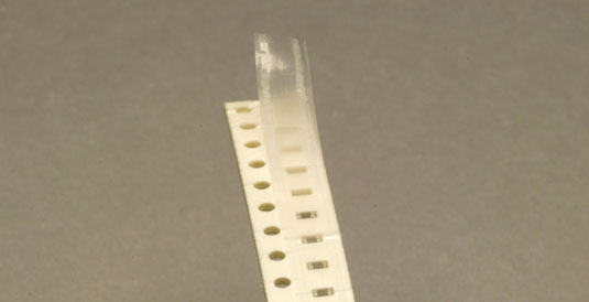
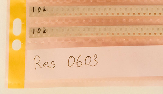
In addition to putting a label on each page, I also like to write on each tape what components are in there so that the information is not lost once the tape is out of its pocket and also so that one can see what the tape contains when it is still sitting in the pocket. I usually write on the back side of the tape at the end from which one is not taking out components. I also try to make sure I start taking out components from the same end as pick-and-place machines do (naturally the outer end of reeled tape), i.e. if the tape has its top side up and its end is pointing away from you, the holes in the tape shall be to the left. Figure 13 below shows the proper end to open a tape and figure 14 shows tapes labeled on the back side.
Figure 13. The proper end to open a tape to match
pick-and-place machines.
Figure 14. Labeling of tapes.
ImprovementsIt is of course possible to improve this design quite significantly. One might e.g. want to create a welder that can weld a full sheet in one go. For my personal needs of component holders, the effort of doing that (mainly sewing all the resistive wire up and down) would not be worth it, but if I were to sell this as a product, it might be worth it. A different approach of making the welder would be to use small SMD resistors (0402 or 0201) as the heating elements and mount them to a specially designed PCB. I did some experiments along these lines and it turned out that mounting the components on a breadboard was not good enough since the solder joints became too big and interfered with the welds. A custom board with proper solder mask would probably work much better. |
![[XLS]](articles/H-Bridge/resources/excel.png) An excel sheet with a template grid
An excel sheet with a template grid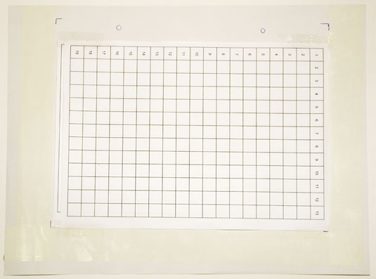
| Updated: 2020-11-24, 12:12:18 |
|