|
|

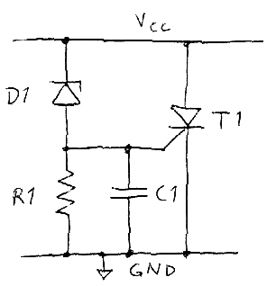
Crowbar circuitsThis article was originally written in March 2008. Additions were made in January 2013. One way to protect a circuit from over-voltages is to use a "crowbar circuit". The idea is to short the power supply rail to ground if an over-voltage is detected and thereby quickly forcing it down to a harmlessly low voltage and blow a fuse or trigger some other over-current protection mechanism. The name of the circuit probably comes from the analogy of throwing a crowbar (or some other thick metal object) across the supply rails to short them. A particularly suitable component to use in a crowbar circuit is the thyristor or SCR (silicon controlled rectifier). This is a semiconductor device that is normally non-conducting, but it can be triggered by a current pulse on the gate terminal and once triggered it conducts from anode to cathode until the current through it is reduced below a low value, often in the range of a few tens of milliamps. When the thyristor conducts, it has a voltage drop of around 1-2 V. Instead of a thyristor, one can also use a triac, which is more or less a bidirectional thyristor. Using a transistor instead of a thyristor or triac would not be so easy, since the power supply necessary to drive the base or gate of the transistor goes away when the supply is shorted, whereas the thyristor or triac needs no further gate drive to stay on once triggered. This is the reason why thyristors and triacs are so widely used in this application. One property of crowbar circuits that is often an advantage is that it becomes very evident that something is wrong and needs fixing once it has triggered. Basic crowbar circuitThe classic crowbar circuit is shown in the figure below.
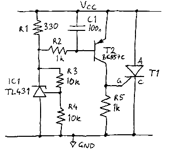
When the supply voltage goes above the zener voltage of the zener diode D1 a current starts to flow through the diode and the resistor R1. If the supply voltage reaches the zener voltage plus the trigger voltage of the thyristor, the thyristor will trigger and bring the supply rail down to 1-2 V above ground. The thyristor will conduct until the current is reduced to close to zero one way or another. The capacitor ensures that the crowbar is not triggered by short voltage spikes on the supply. If the supply of current is unlimited, something will quite quickly start emitting smoke, so for the crowbar to be really successful, the power supply has to be current limited. One way to accomplish this is through a fuse or a polyswitch. Another is to have a current limited supply or preferably a supply with foldback current limiting. One drawback of this basic circuit is that the turn-on voltage cannot be precisely controlled. Zener diodes are only available in discrete voltages, they have a relatively large tolerance (2-5 %), they are temperature dependent and the voltage-current knee is not very sharp. In addition to this, the trigger voltage of the thyristor is also a very poorly controlled parameter that varies widely with temperature. In applications where a low nominal supply voltage shall be protected, the turn-on voltage of the crowbar circuit typically has to be more precisely controlled. Precision crowbar circuitThe below circuit solves the above problems at the cost of some additional complexity. (For further improvements to this circuit see below.)
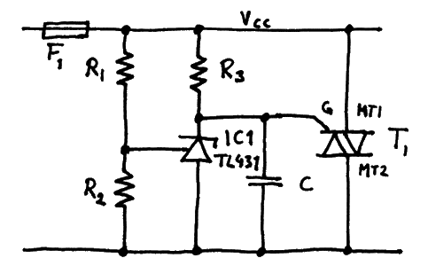
A low-cost adjustable shunt voltage reference, TL431, is used to allow trimming to any voltage between 2.5 and 36V using a voltage divider. Using 1% resistors in the divider R3-R4, the "zener" voltage can be set to a precision of around 1-3% depending on which version of the TL431 is used. Using a TL431 instead of a zener circumvents the problems of the discrete zener voltages available as well as the unsharp knee of zeners. To improve the situation caused by the ill-controlled trigger voltage of thyristors, a transistor T2 is used. This transistor turns on once the emitter-base voltage is above ~0.6V. The turn-on characteristics of the transistor is temperature dependent (as is the current and voltage required to trigger the thyristor), but the uncertainty of the trigger voltage of the total circuit is much reduced compared to the basic circuit. The reference voltage to the TL431 is 2.5V, so with the given component values, the set voltage of the TL431 is 5V and the trigger voltage of the crowbar is around 5.6 - 6.0 V. This could be suitable to protect a 5V-rail. The capacitor C1 reduces sensitivity to short spikes and also reduces the risk of a false triggering if voltage is applied abruptly. di/dt protectionThere are still potential problems with this circuit that have to be taken into account when selecting components. A major concern is the stress that the thyristor is subjected to when it triggers. If it is triggered softly with a current just above the trigger current, it cannot withstand a very quick rise in anode-cathode current. The gate triggers only a small area of the semiconductor die to conduct and it takes some time for the whole thyristor to start conducting. If a lot of current is forced through the thyristor before it has fully triggered, the current concentration can become large enough to destroy or at least degrade the component. This is specified in data sheets as maximum di/dt and can be on the order of 100 A/µs for a 12 A thyristor. In lucky cases, a destroyed thyristor becomes a short circuit, so that it still protects the rest of the circuit from overvoltage, but this cannot be guaranteed. In general, using a larger thyristor makes the crowbar more rugged. Having large capacitors with low ESR (equivalent series resistance) on the rail protected by the crowbar increases the risk of overstressing the thyristor. Especially large ceramic capacitors can deliver huge di/dt pulses. One way to protect the thyristor at the cost of slower turn-on is to insert an inductor in series with the anode. The required value can be calculated from the following formula: U = L*di/dt L = U/(di/dt) In the circuit above we have a trigger voltage of at most 6V while the residual voltage over the thyristor is at least 1V. This gives U = 6V - 1V = 5V. Assuming a maximum allowable di/dt of 100A/µs for the thyristor in use (check the datasheet), we get a minimum inductance of 50 nH, which is a fairly low value. Typically it is not possible to buy power inductors with such low inductance, so a larger value may have to be selected. The inductor only has to function as a good inductor until the thyristor has fully triggered, which might take around 1µs, so the saturation current does not have to be bigger than the current at the time when the thyristor has fully turned on. A conservative estimate of the inductor (and thyristor) current after time t is i = t*(di/dt)max = t*U/L. So the optimization problem here is to select a small and cheap inductor with an inductance value and saturation current that fulfills the above requirements. It is also important to take a look at the DC resistance of the inductor to check that the RDC*I2 power dissipation will not destroy the inductor when the crowbar has triggered. Also the voltage drop across the inductor might be an issue if RDC is too large, but this is probably quite unlikely to be a problem. As an example a Coilcraft LPS6225-122ML (1.2µH, 5.4A, 0.04Ω, 6.2*6.2 mm2) inductor is suitable in our case. This gives a current after 1µs of at most 1µs×5V/1.2µH = 4.2A, thus no saturation before full triggering. Assuming a fuse or polyswitch of 4A, the long-term current can hardly be much more than 5A which gives a maximum power dissipation in the inductor of 1W which it probably is able to handle, although it will become rather hot. The above crowbar circuit can be set to trigger at voltages from around 3.2V and up to 36V by selecting suitable values for R3 and R4. The current into the reference pin of IC1 can be a few microamps, so R4 should not be selected too small if high precision is required. 10 kohm is probably on the high side and should be decreased if higher precision is required. Going below 1 kohm gives diminishing returns. Another TL431-based crowbar circuitIn the datasheet for the TL431 shunt voltage refence there is another crowbar circuit among the application examples. This one flips the thyristor or rather triac on its head and uses it in the third quadrant where the MT1 terminal is at a higher potential than MT2 and a gate current is pulled out of the device when it is to trigger, see the figure below.
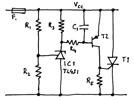
The circuit works like this: When the voltage at the reference input to the TL431 is lower than 2.5V, the TL431 draws at most 400 µA which produces a rather small voltage drop across R3. When Vcc increases such that the voltage at the reference input reaches 2.5V, the regulator starts to try to regulate the voltage by pulling more current through it. This increases the drop across R3 until the gate voltage of the triac is far enough below MT1 (which sits at Vcc) to pull a big enough gate current out of the triac to trigger it. The capacitor C has to be selected such that it will not cause instability (see datasheet). R1 and R2 should have a low enough resistance that the current into the reference pin (4 µA or less) does not contribute a significant error to the voltage divide ratio. R3 should be selected such that a current of 400 µA gives a voltage drop of less than the minimum gate trigger voltage (maybe 0.5 V or so). This circuit is probably more precise than the circuit suggested above and it also has the advantage that it does not need the transistor. It does however only work with a triac and not a thyristor, but this is probably not a significant disadvantage. Improved TL431-based thyristor crowbar circuitBased on the technique used in the above circuit, namely using the TL431 more like a comparator with a built-in reference than as a precision zener diode, the previously described crowbar circuit with a thyristor and a TL431 can be improved. The previous circuit had the (minor) problem that the trip voltage was affected by the temperature dependent base-emitter voltage of a transistor, but that dependence can be circumvented by a minor modification to the circuit. The result is shown in the figure below. One way of describing the difference between the two circuits is that the latter has the transistor and the triac included in the feedback path of the TL431, whereas the former has a tight feedback path that makes the TL431 and its two resistors work as a standalone zener diode.
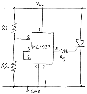
Crowbar controllerThere is a somewhat dated circuit called MC3423 from ON Semiconductor that can be used to control the thyristor of a crowbar with even higher precision while giving a higher gate overdrive current to ensure good turn-on with reduced di/dt problems. The trigger voltage can be set between 4.5 V and 40 V using a resistive divider. The below schematic shows a basic application of the MC3423.
Disadvantages compared to the previous circuits is higher cost, increased power consumption and higher minimum triggering voltage. The size may also be bigger since the MC3423 is not available in any package smaller than SO8. LinksHere are some links to sites that discuss crowbar circuits. |
| Updated: 2016-12-11, 14:28:04 |
|
![[SW flag]](pic/Sw_flag_40.png)

![[UK/US flag]](pic/UK-US_flag_40.png)

