![[SW flag]](pic/Sw_flag_40.png)

![[UK/US flag]](pic/UK-US_flag_40.png)

|
|

Design of AttenuatorsUpdated to include also T-attenuators on 2012-02-12. If you are just looking for the excel sheet that helps with the design of attenuators the link is provided here:
BackgroundIn RF systems it is often necessary to attenuate a signal. This has to be done in an impedance-matched environment where there shall be a minimum of impedance mismatches and reflections. Two popular attenuator topologies are the pi attenuator (so called because the configuration of resistors resembles the Greek letter pi) and the T-attenuator (for its topological similarity with the letter T). The schematic of a pi attenuator is shown in figure 1 below:
Figure 1. The topology of a pi attenuator.
The schematic of a T attenuator is shown in figure 2 below:
Figure 2. The topology of a T attenuator.
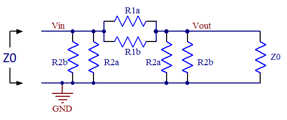
You might wonder why two resistors have the same designator in the figures. This is because we want the attenuators to be symmetrical so that they provides the same function no matter which end of it connects to the load and which connects to the source. There are two requirements on the networks, namely to match the impedance and to provide a specific value of attenuation, so it should be enough with two degrees of freedom. We do therefore not need to keep all three resistor values free and making this observation here makes the derivations easier. Derivation of pi attenuator formulasSo how does one select R1 and R2 for the pi attenuator? The two requirements mentioned above yields one equation each. First we want the impedance looking in from the left to be equal to the system impedance Z0: R2//(R1 + R2//Z0) = Z0 Where // denotes parallel connection of resistors. Simplifying this yields: R1 = 2*R2*Z02/(R22 - Z02) (I) The other requirement is that the network shall provide a certain attenuation. The formula for voltage division yields: Vout = Vin * (R2//Z0) / (R1 + R2//Z0) The attenuation (gain) A is defined as: A = Vout/Vin Combining the latter two formulas yields: R2*Z0*(1-A) = A*R1*( R2 + Z0 ) Inserting (I) in this formula and simplifying yields: R2 = Z0*(1+A)/(1-A) (II) Inserting (II) in (I) and simplifying yields: R1 = Z0*(1-A2)/2A (III) So these are the formulas to obtain the resistor values of a pi attenuator given a certain system impedance and a desired attenuation. Derivation of T attenuator formulasThe resistor values of T attenuators can be derived in a similar manner as for the pi attenuator above. First, let's find out the attenuation (gain) of the network when loaded with the impedance matched load Z0. Using the formula for voltage division twice yields the expression: Vout = Vin * (R2//(R1 + Z0)) / (R1 + R2//(R1 + Z0)) * Z0/(R1 + Z0) Setting the gain A = Vout/Vin yields: A = Vout/Vin = (R2//(R1 + Z0)) / (R1 + R2//(R1 + Z0)) * Z0/(R1 + Z0) (IV) Second, we want the impedance looking in from the left to be equal to the system impedance Z0: R1 + R2//(R1 + Z0) = Z0 Here we can se that the somewhat complicated term R2//(R1 + Z0) appears again just like it did in (IV) and we can use this fact to solve for it to get a simpler expression we can put into (IV) to simplify that equation: R2//(R1 + Z0) = Z0 - R1 (IV) (V) in (IV) now yields: A = (Z0 - R1) / Z0 * Z0/(R1 + Z0) = (Z0 - R1) / (R1 + Z0) (VI) Solving (VI) for R1 yields: R1 = Z0 * (1-A)/(1+A) (VII) We can put this expression for R1 into e.g. (IV) and simplify to get: R2 = Z0 * 2A/(1-A2) (VIII) So these are the formulas to obtain the resistor values of a T attenuator given a certain system impedance and a desired attenuation. Should I use a T attenuator or a pi attenuator?It can be shown that the two attenuator topologies given here have identical port impedances and transfer functions. If one is given a black box (a box that one cannot look into) attenuator and an ohm-meter, it is impossible to determine which topology is in the box as all resistances will be the same. From this one might conclude that it does not matter which of the topologies one decides to implement, but in reality there may be other considerations depending on what resistors are conveniently available in the technology used (thin film vs. thick film) and the attenuation one is after. Parasitics may also play a role at high frequencies when determining which topology is better. In general I would guess the pi attenuator has better frequency response since there is less series inductance in the signal path and also less series inductance in the shunt path. For normal SMD resistors the series inductance is likely to dominate over the parallel capacitance. So the pi version is generally to be preferred if getting the maximum bandwidth is important. Identifying unmarked attenuatorsOccasionally one may encounter an unmarked attenuator and it can be useful to have a quick and easy way of determining what attenuation it has using a simple ohm-meter. The straightforwad method is to measure the resistance from input to output or from input to GND. It is of course trivial to calculate what these resistances will be for a given attenuation when the individual resistor values are known and I included formulas for this in the spread sheet below as well as rows in the table with example values. As mentioned above, there is no difference between the port impedances of ideal pi or T attenuators with the same attenutation. For attenuators with lots of attenuation (say more than 30-40 dB) the ohm-meter method is however not very precise as the measured resistances change very little with changing attenuation. One may then have to resort to actually measuring the attenuation using a network analyzer (if conveniently available) or an ad hoc "DC network analyzer" built from a DC supply that feeds one end of the attenuator and measuring the output voltage at the other end. Applying 1.000V at the input makes it easy to read out the unterminated gain using a voltmeter. Be sure not to overload the attenuator though. Some small attenuators might not be able to withstand even 1W (7V into 50 ohms), but 1V is probably safe for all attenuators. I included the unterminated voltage gain in the spread sheet and table for this purpose. Using standard resistor valuesIn real life one has to stick with standard resistor values and this (as well as component tolerances) will result in non-ideal behavior of the attenuator. To get closer to the ideal values, one can use parallel combinations of resistors like in the figure below:
Figure 3. A pi attenuator with parallel resistors to
get closer to the ideal resistor values using standard values.
There are various ways in which to measure the non-ideality of a given attenuator. One can easily calculate the input impedance and the attenuation using the selected resistor values and compare those to the desired ones. Based on the calculated input impedance, one can also proceed to calculate other figures of merit, like the reflection coefficient (Γ), the voltage standing wave ratio (VSWR) and the return loss (RL). These numbers can be found as: Γ = (Zin - Z0)/(Zin + Z0) RL = -20*log10(|Γ|) VSWR = (1 + |Γ|)/(1 - |Γ|) If Zin > Z0 then this simplifies to: VSWR = Zin/Z0 (when Zin > Z0) If instead Zin < Z0 this formula applies: VSWR = Z0/Zin (when Zin < Z0) The above formulas are used in the following excel sheet to aid in the selection of resistor values for specific values of Z0 and specific values of attenuation:
Ideal and suggested values for some specific 50Ω pi attenuators are also provided in the table below.
ReferencesHere is a link to a page with some additional information about attenutators, including information about other topologies: |
![[XLS]](articles/H-Bridge/resources/excel.png) An excel sheet for attenuator design
An excel sheet for attenuator design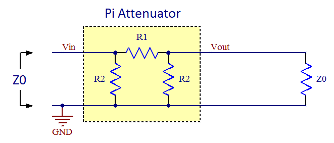

| Updated: 2016-12-11, 14:27:58 |
|