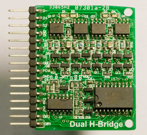
The PCB was manufactured (at ITead Studio) and I soldered the components to it manually. The result can be seen in figure 11 below.

Unfortunately I had made a mistake in the design (the drive signals to the NMOS transistors were not cross connected as they should have been) and I needed to add four patch wires to the board to make it work (not shown in the photo). The schematic and layout files shown in the article do however have this mistake corrected.
Before doing the layout of the H bridge and building it, I prototyped it all on a solderless breadboard (the surface mount MOSFETs I did however put on small PCB prototype boards since they do not lend themselves to direct connection to this kind of breadboard). The breadboard and the finished H bridge PCBA that replaced it is shown in figure 12 below.
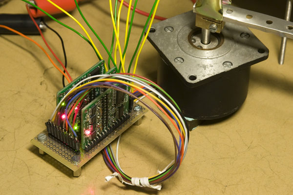
Figure 13 shows a photo of three dual H bridge boards driving one of the 5-phase bipolar stepper motors that I designed the bridge for.

A short movie clip showing three (of which two and a half are used) dual H bridges driving a 5-phase bipolar stepper motor is provided below.
© Per Magnusson, Axotron