After the incandescent bulb of the bicycle light broke for the second time in a few weeks, I thought it was time to retire Edison’s invention and move into the 21st century by replacing it with an LED.
I had a cheap battery powered bike LED light laying around, but I wanted the LED to be powered by the hub dynamo and so I decided to convert it from battery power to dynamo power. The dynamo generates AC current at a voltage and current that depends both on the speed of the bike and on the load that is connected to it, so some circuitry had to be designed and built to suitably drive the LED.
The bike light contained a battery holder for four AAA batteries, a single power LED and a small circuit board containing a glob-top chip, a decoupling capacitor, a small external MOSFET and a connection to a button that could put the LED in one of three modes: off, on and flashing. Text printed on the light said “3W”, but I doubt the LED can actually handle that much power and I also doubt the four small batteries could deliver the close-to-one-amp of current required for 3 W. 300 mA and thus approximately 1 W seemed more reasonable. As a hub dynamo can easily generate more than 300 mA and I wanted to get the full brightness at a reasonably low speed while still not overloading the LED at higher speeds, some form of constant current source was required.
If I had wanted to spend lots of time and development effort on building the perfect dynamo-driven bike LED light, I would probably have opted for a schottky bridge rectifier followed by an elaborate switch-mode converter driving one or more big LEDs, preferably with a control scheme that tries to maximize the power put into the LEDs at lower speeds, while keeping the power constant at higher speeds.
My priorities were however somewhat different with this project. I wanted a quick solution that I could finish in a few hours using components I had available at home. The solution I opted for was to build a bridge rectifier using four 1N4002s and follow it by an LM317 adjustable voltage regulator that drives the LED in series with a 1 ohm power resistor; see schematic below. By setting the output voltage of the LM317 to a suitable value, the 1-ohm resistor limits the current through the LED to the desired 300 mA.
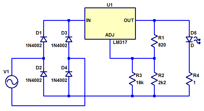
I first measured the LED voltage at 300 mA of current and selected feedback resistors to the LM317 to get a little more than 0.3 V above that value (to account for the voltage drop across the current limiting resistor). That gave me the values for R1 and R2. Then I built the circuit on perf board, but without R3. After that I connected the LED (D5 in the schematic) and tested it while powered from a bench supply. I added R3 as required to reduce the current to 300 mA. Depending on what LED you have and how much current you want to supply it with, you need to adjust the voltage divider R1-R2-R3 accordingly.
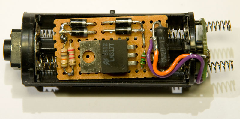
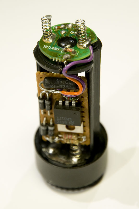
The finished circuit board is shown below while fitted in the battery compartment of the original bike light. The LM317 does not get a lot of cooling, so maybe it will be get quite hot if pedalling fast. If that turns out to be the case, I will have to figure out a way to thermally connect it to the housing.
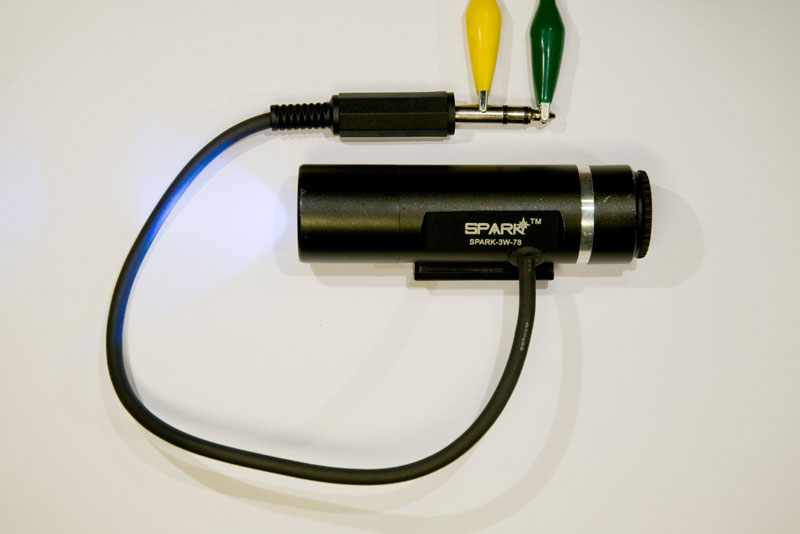
I drilled a hole through the housing and fitted it with a grommet suitable for the cable I intended to use to connect the light to the dynamo. I used a 6.35 mm stereo plug and put a corresponding jack on the bike so that the light could be unplugged and removed. Hopefully these connectors are robust enough to work reliably outdoors for a few years. We will see. The photo below shows the finished light.
A quick test drive demonstrated that the contraption worked as intended. The light flickers when the bike rolls very slowly, but for any reasonable biking speed, the light is stable. Maybe I will build a more powerful bike light in the future, but for now this will do.
Thank you so much for that detailed schematic. I am going to do the same in my bicycle.
I only have one doubt. The circuit is wired directly to the Led contacts, the current will not flow through the old battery circuit.
I was thinking about just dropping the dynamo voltage to 3v DC and limiting wattage as well and soldering the wires to the battery terminals directly, using the circuitry already built in in the headlight. What do you think?
Thank you so much for your time and advice
Hi Robert,
Yes, I bypassed the old circuit intentionally. I think I analyzed what it did and was not very impressed. If I recall correctly, the circuit only toggles between off, blink and on as the push button is pressed. I am pretty sure it did not have any current control capabilities, but relied on the internal resistance of the batteries to limit the current to the LEDs.
What do you see as the advantage of keeping the old circuit? Do you want the blink mode or the push button to toggle between the three modes? You can of course do that and use exactly the same circuit as I have shown above but connect it to the battery terminals instead of to the LED.
Per
Hi Per,
thank you so much for the reply and the help. Just keeping the original circuit I thought it could be easier to develop a simpler schematic (as I have zero abilites in electronics, as I can’t make up the transition from the diagram to building it), just dropping the dynamo voltage to 3v DC (in my case) and the Wattage that 2 simple AA batteries could give. I could use the switch as well (it’s only an on-off thing, but with a dynamo the switch is the dynamo itself).
But as you say, better to have a new complete circuit built, fault free, avoiding a switch which can fail anytime. Now I have to learn which way the diodes go and what every pin in LM317 does (hope the in, out and adj are marked).
Your circuit would fit no problems in my classic headlight casing.
In case the dynamo is Zener-diode equipped, I should take this out, is it correct?
Best regards and thank you so much for your help
Dropping the voltage is precisely what the voltage regulator LM317 does. You can figure out the pinout by googling for the data sheet for the component. The pins are not labeled on the package.
A zener across the dynamo output will not hurt, so you can leave it there. It will limit the voltage to some value that is safe for bulbs (6 V maybe?) and this voltage is enough to power the LM317 in this case. If you remove the zener, the voltage can go up further, but the LM317 can take up to 40 V so it should still be fine, although the power dissipation in the LM317 is the voltage across it times the current through it, so as the input voltage goes up, so does the power dissipation and hence the heat generated.
Hi Per,
Thank you so much for your help. I was trying to find zener-less dynamos desperately and did not succeed. If the zener one makes life easier for the LM317 then much better, as the unit will run cooler (everything will be fitted in the headlight housing, which is plastic, and cooling effect is marginal).
You can’t imagine how difficult is to get hold of these components nowadays.. Will let you know as soon as the device is wired up and running.
Thank you again for your help
Robert